Graphic Operation Terminal F940GOT
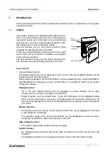
Introduction 1
1-5
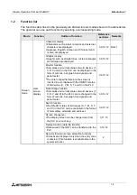
HPP
mode
Program
(list)
§
Programs can be read/written/monitored in the
instruction list program format.
4
Valid in FX
Series
Parameter
§
Parameters for the program capacity, the mem-
ory latch range, etc. can be read/written.
Valid in FX
Series
BFM
monitor
§
Buffer memories (BFMs) in special blocks for the
FX
2N
/FX
2NC
Series can be monitored, and their
set values can be changed.
Valid in
FX
2N
/
FX
2NC
Series
Device
monitor
§
The ON/OFF status of bit devices as well as cur-
rent values and set values of word devices can
be monitored using device Nos. and comment
expression.
Note 1
Current
value/
set value
change
§
Current values and set values of word devices
can be changed using device Nos. and comment
expression.
Forced
ON/OFF
§
Bit devices (X, Y, M, S, T and C) in the PLC can
be forcedly set to ON or OFF.
State
monitor
§
State (S) Nos. in the ON status are automatically
displayed for monitoring (valid only when the
MELSEC FX Series is connected).
Valid in FX
Series
PLC diag-
nosis
§
The error information in the PLC can be read and
displayed.
Valid in FX
Series
Mode
Function
Outline of function
Reference
sections
Remarks
Summary of Contents for F940GOT-LWD-E
Page 1: ...OPERATION MANUAL F940GOT SWD E F940GOT LWD E...
Page 4: ...Graphic Operation Terminal F940GOT 2...
Page 6: ...Graphic Operation Terminal F940GOT 4...
Page 8: ...Graphic Operation Terminal F940GOT 6...
Page 14: ...Graphic Operation Terminal F940GOT Contents vi...
Page 104: ...Graphic Operation Terminal F940GOT Alarm Mode 6 6 12...
Page 148: ...Graphic Operation Terminal F940GOT Creation of Display Screens 9 9 30...
Page 228: ...Graphic Operation Terminal F940GOT Changeover of Display Screen FX PCS DU WIN E 11 11 18...


