Graphic Operation Terminal F940GOT
Additional Functions (in Ver. 3.00 or Later) 14
14-7
14.3
Connection to PC manufactured by Allen-Bradley
When connecting the SLC500 Series PC manufactured by Allen-Bradley, set the communica-
tion parameters and the RS-232C port as follows using an SLC500 Series peripheral tool.
For connection, refer to the hardware manual of the GOT main unit and the instruction manual
of the SLC500 Series.
14.3.1
Setting of communication
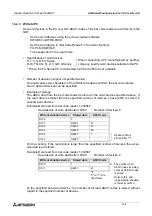
•
Setting of RS-232C (channel 0) parameters
Set the system mode driver (DF1) to "half-duplex slave (DF1)".
Set other parameters to default values (initial values).
•
Channel configuration of DF1 (half duplex slave)
Set the parameters as shown in the table below.
Set all parameters except shaded ones to default values.
•
Setting on GOT
When the connected PC is set to "SLC500 Series" in the screen creation software or "SET-
UP MODE" in the GOT, the following setting is selected.
(The following setting is automatically selected when the PC model is set to "SLC500
Series". You do not have to set them manually.)
Parameter
Set value
Diagnostic File
-
Baud Rale
19200
Parity
Even
Duplicate Packet Delection
Disabled
Station Adress
0
Error Delection
BCC
Poll Timeout
50
RTS Off Delay
0
RTS Send Delay
0
Message Retries
3
Control Line
No Handshaking
EOT Suppression
No
Baud rate
19200
Data length
8 bits
Stop bit
1 bit
Parity bit
Even
Control method
None
Summary of Contents for F940GOT-LWD-E
Page 1: ...OPERATION MANUAL F940GOT SWD E F940GOT LWD E...
Page 4: ...Graphic Operation Terminal F940GOT 2...
Page 6: ...Graphic Operation Terminal F940GOT 4...
Page 8: ...Graphic Operation Terminal F940GOT 6...
Page 14: ...Graphic Operation Terminal F940GOT Contents vi...
Page 104: ...Graphic Operation Terminal F940GOT Alarm Mode 6 6 12...
Page 148: ...Graphic Operation Terminal F940GOT Creation of Display Screens 9 9 30...
Page 228: ...Graphic Operation Terminal F940GOT Changeover of Display Screen FX PCS DU WIN E 11 11 18...

