Graphic Operation Terminal F940GOT
Start up 2
2-6
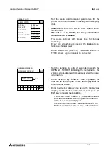
• Set the serial communication parameters for the
printer used to print out alarm messages and sampling
data.
• Make sure to set "PRINTER" to "USE" when a printer
is connected.
When it is set to "USE", the two-port interface
function is not available.
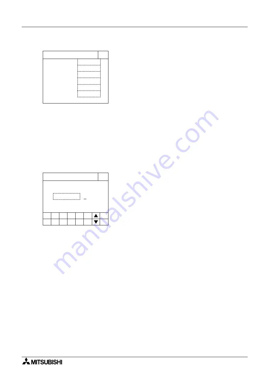
• The areas enclosed with broken lines function as
touch keys.
Every time a touch key is pressed, the displayed con-
tents are changed over.
• When "LINK PORT (RS232C)" is selected on the PLC
TYPE screen, a printer cannot be connected.
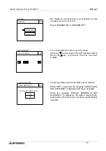
• Set the duration in units of seconds in which the
OPENING SCREEN indicating the model name, the
version, etc. is displayed immediately after the power
is turned on.
• When the touch key "DISPLAY TIME" is pressed, the
time can be set using the ten-key pad displayed at the
bottom of the screen.
• Enter the desired display time using the ten-key pad
displayed at the bottom of the screen, then press the
ENT key to register the input time.
* If "DISPLAY TIME" is set to "0", the screen mode is
selected immediately after the power is turned on
and a user screen is displayed.
It is recommended to set 1 second or more for the
FX Series and 4 seconds or more for the A Series.
9600 bps
7 bit
1 bit
[ SERIAL PORT ]
END
[ SERIAL PORT ]
Even
XON/XOFF
DON'T USE
SPEED:
DATA BIT:
STOP BIT:
PARITY:
HANDSHAKING:
PRINTER:
DISPLAY TIME
4 SEC.
[ OPENNING SCREEN ]
END
[ OPENNING SCREEN ]
5
6
7
8
9
-
CLR
0
1
2
3
4
ENT
Summary of Contents for F940GOT-LWD-E
Page 1: ...OPERATION MANUAL F940GOT SWD E F940GOT LWD E...
Page 4: ...Graphic Operation Terminal F940GOT 2...
Page 6: ...Graphic Operation Terminal F940GOT 4...
Page 8: ...Graphic Operation Terminal F940GOT 6...
Page 14: ...Graphic Operation Terminal F940GOT Contents vi...
Page 104: ...Graphic Operation Terminal F940GOT Alarm Mode 6 6 12...
Page 148: ...Graphic Operation Terminal F940GOT Creation of Display Screens 9 9 30...
Page 228: ...Graphic Operation Terminal F940GOT Changeover of Display Screen FX PCS DU WIN E 11 11 18...


