Graphic Operation Terminal F940GOT
Alarm Mode 6
6-6
6.2
Operation when alarms have occurred
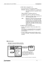
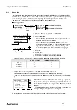
The figure below shows the outline of operation performed when alarms have occurred.
When a bit device assigned as an alarm device becomes ON (OFF
à
ON), the GOT recog-
nizes that an alarm has occurred.
When two or more alarms have occurred, the GOT recognizes them one by one in turn.
•
The ON/OFF status of alarm devices are read every time communication is performed (at
every 300 to 400 ms) between the GOT and the PLC when the FX-PCS-DU/WIN-E is used
or at the time interval (variable within the range of 600 to 100 ms) set by "Monitor Cycle" in
"Alarm History Common Setting" when the SW
¨
D5C-GOTRE-PACK is used.
•
Inside the GOT, alarm messages are displayed (overlaying on the user screens) or a speci-
fied screen is displayed in the screen mode, alarm devices are stored in the history and
their frequencies are counted in the alarm mode in accordance with the contents set prelim-
inarily in the screen creation software.
•
When two or more alarms have occurred, they are sorted in the ascending order of alarm
device No. in the alarm list and stored in the alarm history in the order of occurrence.
When the SW
¨
D5C-GOTRE-PACK is used, the alarm history can be stored in the order of
occurrence (from the oldest one) or in the reverse order of occurrence (from the latest one).
•
In the alarm history and the alarm frequency, up to the following number of cases can be
stored respectively. They are stored even if the power is turned off.
Alarm history
: Up to 1,000 cases
If 1,001 or more alarms have occurred, the record is updated while excessive
alarms are deleted from the oldest one. (When the SW
¨
D5C-GOTRE-PACK
is used, it can be set so that excessive alarms are deleted from the latest one.)
Alarm frequency: Up to 32,767 cases
Even if more alarms have occurred, 32,767 cases remain stored.
•
If an alarm has occurred in any mode other than the screen mode, the occurrence history
and the frequency are recorded. The display can be changed over to a specified screen,
and the alarm can be output to the printer. (However, the alarm message does not overlay
the base screen displayed at that time.)
Screen mode
Alarm 0
When many alarms have
occurred, corresponding
alarm messages are
displayed in the ascending
order of device No.
Instead of an alarm
message, a specified
screen can be displayed.
DISPLAY
STATUS
screen
Alarm 0
Alarm 3
Alarm mode
n
n+1
n+2
n+3
0
1
2
3
254
255
n+254
n+255
ALARM
HISTORY
screen
Alarm 0
Alarm 3
ALARM
FREQUENCY
screen
Alarm 01
Alarm 10
Alarm 20
The GOT monitors bit devices
in the PLC, and recognizes
that alarms have occurred
when they become ON.
(Communication is performed
at every 300 to 400 ms.)
n
n+1
n+2
n+3
n+254
n+255
ON
OFF
OFF
ON
Up to 256 consecutive
alarm devices
Sequence program
OFF
OFF
n+255
Output to the printer
(Alarm devices and alarm
messages are printed.)
GOT
PLC
Alarm
message
Device
No.
ON/OFF
status
Device
No.
n
Summary of Contents for F940GOT-LWD-E
Page 1: ...OPERATION MANUAL F940GOT SWD E F940GOT LWD E...
Page 4: ...Graphic Operation Terminal F940GOT 2...
Page 6: ...Graphic Operation Terminal F940GOT 4...
Page 8: ...Graphic Operation Terminal F940GOT 6...
Page 14: ...Graphic Operation Terminal F940GOT Contents vi...
Page 104: ...Graphic Operation Terminal F940GOT Alarm Mode 6 6 12...
Page 148: ...Graphic Operation Terminal F940GOT Creation of Display Screens 9 9 30...
Page 228: ...Graphic Operation Terminal F940GOT Changeover of Display Screen FX PCS DU WIN E 11 11 18...

