Graphic Operation Terminal F940GOT
HPP Mode 4
4-19
4.7
BFM MONITOR
The contents of buffer memories can be read / written to by special blocks connected to the
FX
2N
/FX
2NC
PLC.
The model of the connected special blocks are automatically recognized and the contents of
the buffer memories are displayed together with the name and the unit. Accordingly, operations
can be checked without performing any manual procedure.
•
Applicable special blocks
Analog input: FX
2N
-4AD, FX
2N
-4DA, FX
2N
-4AD-PT and FX
2N
-4AD-TC
High-speed counter: FX
2N
-1HC
Pulse output: FX
2N
-1PG
u
u
u
u
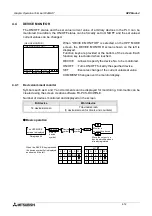
Basic operation
•
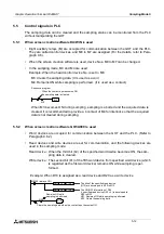
Serial block Nos. are assigned to special blocks connected to the FX
2N
/FX
2NC
Series basic
unit. "0" is assigned to the special block nearest to the basic unit. Up to eight special blocks
can be monitored and set.
For each available special block, its model name is displayed.
For each unavailable special unit (such as the FX-10GM and the FX-20GM), "UNKNOWN"
is displayed.
When any special block is not connected, "NONE" is displayed.
•
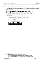
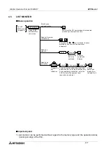
When a special block to be monitored is selected, the buffer memory list is displayed as
shown below.
•
The set value can be entered using the touch keys
on the screen.
To enter a numeric, use the ten-key pad displayed
at the bottom of the screen.
•
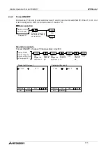
The DETAIL key is provided for the FX
2N
-1PG, etc.
so that the contents of the buffer memories can be
monitored to details.
n
n
n
n
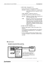
Important point
•
Setting of the buffer memories
The contents of the buffer memories set using this function are treated as follows when the
power of the special block is turned off.
-
FX
2N
-4AD, FX
2N
-4DA, FX
2N
-4AD-PT and FX
2N
-4AD-TC
The setting contents are saved in the built-in EEPROM, and kept stored even if the power
is turned off.
-
FX
2N
-1HC and FX
2N
-1PG
The setting contents are saved in the built-in RAM, so they are deleted when the power is
turned off.
When the buffer memories have been set using a sequence program (TO instruction), the set-
ting by the sequence program has the priority.
Use the buffer memory monitor function to perform the initial setting of special blocks and mon-
itor buffer memories.
5
(BLOCK 1)
[ 4DA ]
END
6
0
1
7
8
2
3
9
4
CLR
ENT
OUTPUT MODE
OUTPUT DATA
DATA HOLDING
OFFSET DATA
GAIN DATA
G/O ADJUST
ERR STATUS UNDEFINED
(0mA to 20mA)
[ 0. 000](mA)
[ 0. 000](mA)
[ 20. 000](mA)
HOLD
FORBID
CH1
CH2
CH3
CH4
INIT
Summary of Contents for F940GOT-LWD-E
Page 1: ...OPERATION MANUAL F940GOT SWD E F940GOT LWD E...
Page 4: ...Graphic Operation Terminal F940GOT 2...
Page 6: ...Graphic Operation Terminal F940GOT 4...
Page 8: ...Graphic Operation Terminal F940GOT 6...
Page 14: ...Graphic Operation Terminal F940GOT Contents vi...
Page 104: ...Graphic Operation Terminal F940GOT Alarm Mode 6 6 12...
Page 148: ...Graphic Operation Terminal F940GOT Creation of Display Screens 9 9 30...
Page 228: ...Graphic Operation Terminal F940GOT Changeover of Display Screen FX PCS DU WIN E 11 11 18...


