background image

COOLING SYSTEM 

2-3 


Installation


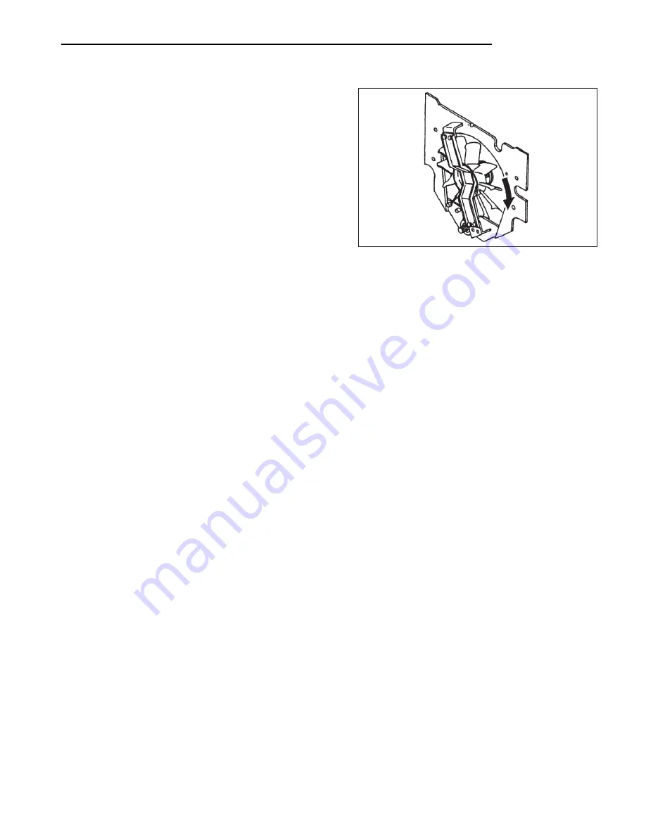
To install, follow the reverse of removal procedure and take 
the following steps:


(1)


After  removing  the  belt,  turn  the  fan  to  examine  the 
bearings  for  abnormal  noise.  Replace  the  bearings  if 
abnormally  noisy.


(2)


After  installing  the  belt,  push  it  inward  midway 
between  the  pulleys  to  make  sure  the  tensioner  pulley 
moves  freely  before  tightening  the  tensioner  lock  bolt 
and mounting  bolt.


206420


Summary of Contents for FGC15K

Page 1: ...0011 up FGC25K HO AF82C 90011 up AF81D 00011 up AF82D 90011 up AF81E 00011 up AF82E 90011 up FGC20K AF82C 00011 up FGC30K AF83C 00011 up AF82D 00011 up AF83D 00011 up AF82E 00011 up AF83E 00011 up FGC20K HO AF82C 90011 up AF82D 90011 up AF82E 90011 up For use with 4G63 4G64 Engine Service Manual and Liquefied Petroleum Gas Supplements 99719 70150 ...

Page 2: ...right to change specifications or design without notice and without incurring obligation For the items pertaining to the engines refer to the following service manuals 4G63 4G64 Gasoline Engine Service Manual Pub No 99729 74120 For use with both gasoline and LP Gas engines 4G63 4G64 LP Gas Supplement Pub No 99729 75100 For use with LP Gas units with a D in the chassis serial number 4G63 4G64 LP Ga...

Page 3: ...4 Rc1 8 Taper pipe thread internal 1 8 inch formerly PT1 8 G1 4A Straight pipe thread external 1 4 inch formerly PF1 4 A Rp1 8 Straight pipe thread internal 1 8 inch formerly PS1 8 Clearance between cylinder and piston A 0 020 to 0 105 0 00079 to 0 00413 B 0 15 0 0059 gram is followed by and Suggestions for Each disassembly dia Disassembly sequence disassembly Disassembly sequence Sequence 1 Cover...

Page 4: ...om steps walkways or work platforms before using Always face truck when using steps ladders and walkways When it is not possible to use the designed access system provide ladders scaffolds or work platforms to perform safe repair operations 6 To avoid back injury use a hoist when lifting components which weigh 23 kg 50 lb or more Make sure all chains hooks slings etc are in good condition and are ...

Page 5: ...If a guard or shield must be removed to perform the repair work use extra caution 17 Always support the mast and carriage to keep carriage or attachments raised when maintenance or repair work is performed which requires the mast in the raised position 18 Loose or damaged fuel lubricant and hydraulic lines tubes and hoses can cause fires Do not bend or strike high pressure lines or install ones wh...

Page 6: ...unction Removal and Installation Rear Axle Assembly Steering Cylinder Adjustment Troubleshooting Service Data BRAKE SYSTEM Structure and Functions Disassembly and Reassembly Inspection and Adjustment Troubleshooting Service Data STEERING SYSTEM Structure and Functions Removal and Installation Streering Gear Troubleshooting Service Data FUEL SYSTEM Outline of Dual Fuel Type HYDRAULIC SYSTEM Hydraul...

Page 7: ...1 GENERAL INFORMATION Vehicle Exterior 1 1 Models 1 1 Serial Number Locations 1 2 Dimensions 1 4 Technical Data Standard Models 1 6 ...

Page 8: ......

Page 9: ... 4G63 gasoline engine FGC18K AF81C 00011 up AF81D 00011 up AF81E 00011 up FGC20K AF82C 00011 up AF82D 00011 up AF82E 00011 up FGC25K AF82C 00011 up AF82D 00011 up AF82E 00011 up FGC20K HO AF82C 90011 up AF82D 90011 up AF82E 90011 up Mitsubishi 4G64 gasoline engine FGC25K HO AF82C 90011 up AF82C 90011 up AF82C 90011 up FGC30K AF83C 00011 up AF83C 00011 up AF83C 00011 up ...

Page 10: ...GENERAL INFORMATION 1 2 Serial Number Locations Nameplate Mast serial number Transmission serial number Engine serialnumber 207070 ...

Page 11: ...GENERAL INFORMATION 1 3 Memo ...

Page 12: ...GENERAL INFORMATION 1 4 Dimensions 207071 G C K L D E J A H I B P N M F O ...

Page 13: ...verall length 2055 80 9 2083 82 0 2227 87 5 2287 90 2455 96 7 G Overall width outside of tires 945 37 5 1055 41 5 1105 43 5 H Overall height to top of mast lowered 2105 83 2110 83 5 2155 85 I Overall height to top of overhead guard 2022 79 6 2060 81 1 J Overall height to top of mast extended 4550 179 4565 180 4535 176 K Trend front 793 31 2 877 34 5 902 35 5 L Trend rear 826 32 5 922 36 3 897 35 5...

Page 14: ...nded 4550 179 4565 180 4535 176 To top of overhead guard 2022 79 6 2060 81 1 2060 81 1 Wheel base mm in 1190 46 9 1350 53 1 1500 59 1 Tread mm in Front 793 31 2 877 34 5 902 35 5 Rear 826 32 5 922 36 3 897 35 5 897 35 5 Load moment constant mm in 376 14 8 399 15 7 412 16 2 Rear overhang mm in 479 18 9 507 20 0 475 18 7 532 20 9 529 20 8 Ground clearance at frame 95 3 7 130 5 1 130 5 1 Tire size mm...

Page 15: ...ric Distributor Type Non contact point type C E I Non contact point type C E I Non contact point type C E I Make Mitsubishi Electric Mitsubishi Electric Mitsubishi Electric Spark advancer Centrifugal pneumatic type Centrifugal pneumatic type Centrifugal pneumatic type Spark plugs Type W14EX U W14EX U W14EX U Make Denso Denso Denso Size mm in 14 1 25 0 55 0 049 14 1 25 0 55 0 049 14 1 25 0 55 0 049...

Page 16: ...ift Hydraulic column shift Hydraulic column shift Ratios Forward 2 913 2 913 2 913 Reverse 2 913 2 913 2 913 Reduction gear Type of gears Skew bevel Skew bevel Skew bevel Ratio 4 571 4 571 4 571 Differential Axle housing Banjo Banjo Banjo Type of gears number Gears Straight bevel 2 Straight bevel 2 straight bevel 2 Pinions Straight bevel 2 Straight bevel 2 Straight bevel 2 Steering system Type Ful...

Page 17: ... 0 185 0 71 2361 0 490 18142 0 5 185 0 71 2361 0 Flow regulator valve Type Variable Variable Variable Regulated flow rate liter cu in min 50 3 3051 183 65 3 3967 183 75 3 4577 183 Lift cylinders mm in ID 45 1 77 50 1 97 55 2 17 Stroke 1650 64 96 1650 64 96 1600 62 99 Tilt cylinders mm in ID 63 2 48 70 2 76 80 3 15 Stroke 96 3 78 111 4 37 111 4 37 Hydraulic tank capacity approx liter U S gal 21 5 5...

Page 18: ...GENERAL INFORMATION 1 10 2 COOLING SYSTEM Structure and Function 2 1 Removal and Installation 2 2 Fan Belt Removal 2 2 Inspection and Adjustment 2 4 Fan Belt Inspection 2 4 Fan Belt Adjustment 2 4 ...

Page 19: ...e cooling fan is installed inside the engine compartment This helps minimize radiator core clogging and retain high cooling efficiency even in continuous operation for hours The radiator s lower tank has a built in transmission oil cooler 209479 ...

Page 20: ...nce 1 Fan guard 2 Tensioner Tensioner pulley 3 Support Cooling fan 4 Universal joint 5 Fan belt Start by Remove the engine hood and gas filled cylinder Suggestions for Removal Make sure the muffler engine and exhaust pipe is cool enough to touch with your hand 206419 ...

Page 21: ...eps 1 After removing the belt turn the fan to examine the bearings for abnormal noise Replace the bearings if abnormally noisy 2 After installing the belt push it inward midway between the pulleys to make sure the tensioner pulley moves freely before tightening the tensioner lock bolt and mounting bolt 206420 ...

Page 22: ... tensioner lock bolt and mounting bolt 2 Insert a small diameter bar or screwdriver into the tension adjustment hole for leverage and adjust the belt tension 3 Adjust the belt so that its deflection is 16 mm 0 6 in when the belt is pushed downward with 98 N 10 kgf 22 lbf force exerted midway between the fan pulley and tensioner pulley 4 Tighten the tensioner lock bolt and mounting bolt 5 After the...

Page 23: ...3 2 Console Box 3 2 Components in Console Box 3 3 Combination Meter 3 4 Major Electrical Components 3 5 Starter Switch with Anti Restart Lock 3 5 Lighting Switch 3 6 Fuse Box 3 7 Spare Terminals 3 7 Battery Maintenance 3 8 Lamp Bulb Specifications 3 9 Troubleshooting 3 10 Electrical Schematic 3 15 ...

Page 24: ......

Page 25: ...urmeter 5 OK monitor 6 Starter switch 7 Lighting switch 8 Fuse box OK Monitor No Indicator light OFF ON or flickering Remarks 1 Powershift transmission oil temp indicator light Normal Overheating Option 2 Air cleaner element indicator light Normal Clogged Option 3 Brake fluid level indicator light Normal Low 4 Engine oil pressure indicator light Normal Low 5 Alternator not charging indicator light...

Page 26: ... the choke cable on the engine side 2 Remove screws 2 four securing the cover 3 Remove screws 3 six and separate the front and rear panels 4 Remove screws 4 four securing the instrument panel Reassembly To reassemble the console box follow the reverse of disassembly procedure To replace the instrument panel bulbs remove screws 3 and 4 NOTE 3 2 4 1 206422A ...

Page 27: ...ELECTRICAL SYSTEM 3 3 Components in Console Box 1 Power relay 2 Power relay 3 Turn signal relay 4 Lighting switch 5 Starter switch 6 Fuses 206423A ...

Page 28: ...it 8 Bulb 9 Socket Reassembly To reassemble the combination meter follow the reverse of disassembly procedure Bulb Replacement For bulb replacement remove the socket from the printed circuit by turning it to the left For configuration of the indicator lights refer to OK Monitor Be careful not to damage the printed circuit when disassembling the combination meter CAUTION 206480 ...

Page 29: ... with Anti Restart Lock This switch has a built in anti restart lock so the key cannot be turned from ON to START position while the engine is running Key position Terminal B M S Component Fuse box battery alternator Fuse box fuel cut solenoid Starter neutral switch powershift transmission models OFF ON START ...

Page 30: ...position 8 8 Stroke 0 3 0 3 Unit mm in 206481 Connection Chart Lighting Switch Terminal Knob Component position OFF B Battery fuses T Tail lamps licence plate lamp instrument lamp H Working lamps option P Head lamps 1st position 2nd position ...

Page 31: ...ment panel lamps E 15 A Head lamps F 10 A Spare fuse G 10 A Horn H 15 A Fuel pump relay J 10 A Engine ECU Spare Terminals The spare terminal cord extends from the fuse box in the console box Another spare terminal is located on the chassis side main harness Removing the console box rear panel will expose this spare terminal which is fastened to the harness protector with vinyl tape Cord color Lg y...

Page 32: ...tilled water is necessary every month or so the battery is overcharged If addition is not required for more than 3 months it is likely that the battery is inadequately charged 3 Charging precautions 1 In slow charging the charging current should be about 1 10 the capacity of the battery to be charged 2 In quick charging the battery capacity in ampere should not be exceeded 3 During charging adjust...

Page 33: ...27 Combination lamps front Turn signals 2 Amber 27 Option Clearance lamps 2 Frosted 10 Option Combination lamps rear Turn signals 2 Amber 23 Option Turn and stop lamps 2 Red 8 23 Option Back up lamps 2 Frosted 10 Option Workiing lamps front and rear 4 Frosted 55 Option Instrument panel lamps Monitor indicator lights 9 Frosted 3 205943A ...

Page 34: ...or short in circuit Repair or replace Gauge internally defective Replace Gauge unit defective Replace Gauge or gauge unit not of the type Replace called for Loose terminal connection Retighten Gauge unit poorly grounded Repair Gauge internally defective Replace Gauge unit defective Replace Short or open circuit in wiring between Repair gauge and gauge unit Gauge unit defective Replace Gauge intern...

Page 35: ...ve Replace Turn signal relay defective Replace Bulbs burnt out Replace Wrong wattage of bulbs Replace Bulbs burnt out Replace Turn signal relay defective Replace Wrong wattage of bulbs Replace Turn signal relay defective Replace Backup lamp switch defective Correct if improperly installed replace if internally defective Bulbs burnt out Replace Fuse blown out Check and replace Open or short in circ...

Page 36: ...DOWNLOAD COMPLETE MANUAL HERE ...

Reviews: