background image

MITSUBISHI
INVERTER
Instruction Manual

FR-EPN

 Communications

Option Unit

Summary of Contents for FR-EPN

Page 1: ...MITSUBISHI INVERTER Instruction Manual FR EPN Communications Option Unit...

Page 2: ...ii DeviceNet is a registered trademark of Open DeviceNet Vendor Association ODVA DeviceNetManager is a trademark of Allen Bradley Company Inc...

Page 3: ...dangerous voltage It informs you of high voltage conditions situation and locations that may cause death or serious injury if you do not follow precautions NOTES inform you of situations or condition...

Page 4: ...allows the inverter to be connected to a network adhering to the DeviceNet communications protocol Some important features are highlighted below Data rates of 125K baud 250K baud and 500K baud are se...

Page 5: ...ET MODE AND PARAMETER SETUP 10 3 3 CONNECTION AND DISCONNECTION 11 4 OPERATION 12 4 1 OPERATION MODES 12 4 2 OPERATION MODE SELECTION 12 4 3 FUNCTIONS AVAILABLE IN OPERATION MODES 13 4 4 INPUT FROM DE...

Page 6: ...21 6 3 I O ASSEMBLIES OBJECT CLASS 04 21 6 4 DEVICENET CONNECTION OBJECT CLASS 0X05 22 6 5 MOTOR DATA OBJECT CLASS 0X28 25 6 6 CONTROL SUPERVISOR CLASS 0X29 26 6 7 AC DRIVE CLASS 0X2A 27 6 8 A200E EX...

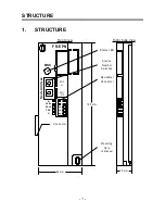
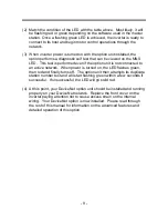
Page 7: ...1 1 STRUCTURE FR EPN Node Address S W 2 x1 S W 1 x10 MNS 193 mm 44 mm V CAN SHLD CAN V Connector DeviceNet Connector Station Number Switches Status LED Mounting Hole 2 places 25 mm v Front View Right...

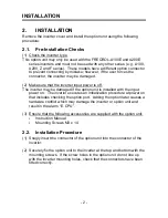
Page 8: ...ed if the option unit is installed with the input power on The inverter executes an initialization procedure at power on that includes checking the option port Adding the option later causes a hardwar...

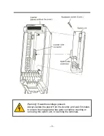
Page 9: ...rning Hazardous voltage present Always isolate the power from the inverter and wait 5 minutes to ensure the charge lamp has gone out before inserting or removing this option unit or touching the termi...

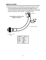
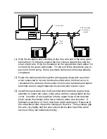
Page 10: ...this cable by the DeviceNet standard is 10 feet On one end of the cable install a connector compatible with the trunk cable and leave free wires on the other end See figures below To FR EPN To Networ...

Page 11: ...ected to inverter terminals so that when the front cover is reinstalled the cables to the inverter control circuit terminals and option terminals are not caught between the inverter and inverter cover...

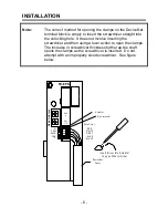
Page 12: ...er and then using a lever action to open the clamps The increase in screwdriver thickness further up the shaft opens the clamps as the screwdriver is inserted Do not attempt with an improperly sized s...

Page 13: ...t the switches and turn power back on to change the node address 2 It is now safe to apply power to the inverter and run it in PU or external mode provided that any external inverter control cables no...

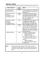
Page 14: ...on unit for communication LED holds this state during communication also Connection Time Out Flashing Red Master designated option unit for communication LED Green state but then sent no messages with...

Page 15: ...ion unit is not connected to an active network When power is turned on the LED flashes green then red and finally turns off The option unit then attempts its duplicate station number test and will sta...

Page 16: ...change the speed manually via the parameter unit refer to the description of Pr 118 3 2 Net Mode and Parameter Setup 1 The inverter must be in Net Mode for motor control operations through the network...

Page 17: ...tes somewhat independently of the inverter in that a master may connect or disconnect while the inverter is in PU mode However motor control commands from the network will not be recognized unless the...

Page 18: ...ter is via commands from a DeviceNet master However FR EPN specific parameters 123 and 124 can be used to select external control for forward reverse stop and output frequency setting 4 2 Operation Mo...

Page 19: ...viceNet operation command yes 1 no no output frequency setting yes 1 no no monitor yes yes yes parameter write yes while stopped 3 no 3 no 3 parameter read yes yes yes inverter reset yes 2 no no exter...

Page 20: ...arameters are supported In addition the parameters listed in the Option specific Parameter section of this specification are supported 4 5 Output from Inverter to DeviceNet 4 5 1 Inverter Status Inver...

Page 21: ...settings which may be needed to read parameters using the PU or other communications option cards e g Prs 61 64 and 201 230 4 6 Operation on Alarm Occurrence The following table shows the behavior of...

Page 22: ...OPERATION 16 4 7 Inverter Reset Inverter reset behavior is as noted above...

Page 23: ...118 To support the FR EPN one new parameter was created Pr 118 It is described below Pr No Function Setting Range Minimum Increment Default Setting 118 DeviceNet Startup Data 0 to 65535 1 1343 This p...

Page 24: ...tance attribute 2 Baud Rate 0 125 kbps 1 250 kbps 2 500 kbps same as attribute semantics 0 Device Address value of DeviceNet Object class code 0x03 instance attribute 1 MAC ID node address range is 0...

Page 25: ...1 External terminal 0 DeviceN et ext ext ext ext ext DN au x both ext ext ext 1 External terminal 1 External terminal ext ext ext ext ext ext ext ext ext ext both ext ext ext Note ext control is via i...

Page 26: ...um Instance Word 1 6 Get Maximum Class Attributes Word 7 7 Get Maximum Instance Attributes Word 7 6 1 2 Class 0x01 Services Instance 0 Service 0x0E Get Attribute Single 6 1 3 Class 0x01 Instance Attri...

Page 27: ...Set Bus Off Counter 5 Get Allocation Information 8 Get MAC ID Switch Value 9 Get Baud Rate Switch Value 00 6 2 4 Class 0x03 Instance Services Instance 1 Service 0x4B Allocate 0x4C Release 0x0E Get At...

Page 28: ...Bit 6 Bit 5 Bit 4 Bit 3 Bit 2 Bit 1 Bit0 0x46 0 Run 1 Fwd Faulte d 1 2 Speed Actual Low Byte 3 Speed Actual High Byte 6 3 4 Input Instance 71 3 9 5 AC Drive Profile Instance Byte Bit 7 Bit 6 Bit 5 Bit...

Page 29: ...ction Path 15 Get Consumed Connection Path Length 0 16 Get Consumed Connection Path 6 4 4 Class 0x05 Instance Attributes Instance 2 Polled I O Access Attribute Value 1 Get State 2 Get Instance Type 1...

Page 30: ...0 14 Get Produced Connection Path 15 Get Consumed Connection Path Length 0 16 Get Consumed Connection Path 6 4 6 Class 0x05 Instance Attributes Instance 5 Explicit Messaging Access Attribute Value 1 G...

Page 31: ...n Size 7 8 Get Consumed Connection Size 7 9 Get Set Expected Pack Rate 12 Get Watchdog Action 1 13 Get Produced Connection Path Length 0 14 Get Produced Connection Path 15 Get Consumed Connection Path...

Page 32: ...ice 0x0E Get Attribute Single 0x10 Set Attribute Single 6 6 Control Supervisor Class 0x29 6 6 1 Class 0x29 Attributes Instance 0 None 6 6 2 Class 0x29 Services None 6 6 3 Class 0x29 Instance Attribute...

Page 33: ...2A Instance Attributes Instance 1 AC Profile Compatible Access Attribute Value 1 Get One 1 3 Get At Reference 4 Get Set Net Reference 6 Get Set Drive Mode 7 Get SpeedActual 8 Get Set SpeedRef 9 Get Cu...

Page 34: ...tor 45 Get Brake Duty 46 Get Converter Voltage 47 Get Motor Torque 48 Get Running Speed 49 Get Output Voltage 50 Get Output Current 51 Get Output Frequency 52 Get Run Status 53 Get Alarm History 1 54...

Page 35: ...999 90 Volt 120 Get Set acc decel ref freq 60 00 Hz 121 Get Set Acc Decel Time Increment 0 122 Get Set Stall Prevention Operation 15 00 123 Get Set High Speed Stall Prevent 999 90 124 Get Set Multi S...

Page 36: ...e Acceleration 999 9 163 Get Set Reference I for Intelligent Mode Deceleration 999 9 164 Get Set Starting F for Elevator 999 9 Hz 165 Get Set Retry Selection 0 166 Get Set Start Prevention Operation 6...

Page 37: ...None 6 8 2 Class 0x66 Services None 6 8 3 Class 0x66 Instance Attributes Instance 1 A200E Special Functions Function Access Attribute Default Value 1 Fn123 Get Set Operation Command Source Net 2 Fn124...

Page 38: ...24 Fn205 Dir Get Set Program Setting 5 Direction 0 25 Fn205 Freq Get Set Program Setting 5 Frequency 999 9 Hz 26 Fn205 Time Get Set Program Setting 5 Time 0 00 Time 27 Fn206 Dir Get Set Program Setti...

Page 39: ...m Setting 15 Direction 0 55 Fn215 Freq Get Set Program Setting 15 Frequency 999 9 Hz 56 Fn215 Time Get Set Program Setting 15 Time 0 00 Time 57 Fn216 Dir Get Set Program Setting 16 Direction 0 58 Fn21...

Page 40: ...ion 0 85 Fn225 Freq Get Set Program Setting 25 Frequency 999 9 Hz 86 Fn225 Time Get Set Program Setting 25 Time 0 00 Time 87 Fn226 Dir Get Set Program Setting 26 Direction 0 88 Fn226 Freq Get Set Prog...

Page 41: ...tage Bias Percent 0 0 107 Fn903 Freq Get Set Freq Voltage Gain Freq 60 00 Hz 108 Fn903 Get Set Freq Voltage Gain Percent 97 0 109 Fn904 Freq Get Set Freq Current Bias Freq 0 00 Hz 110 Fn904 Get Set Fr...

Page 42: ...et configuration software which uses the EDS file to guide a user through the configuration process of a particular device One such configuration package is Allen Bradley s DeviceNetManager This is a...

Page 43: ...Fr eq AC DC Drive attribute 103 4 Multi Speed Setting High Speed AC DC Drive attribute 104 5 Multi Speed Setting Middle Speed AC DC Drive attribute 105 6 Multi Speed Setting Low Speed AC DC Drive attr...

Page 44: ...AC DC Drive attribute 122 23 High Speed Stall Prevention Operation Level AC DC Drive attribute 123 24 Multi Speed Setting Speed 4 AC DC Drive attribute 124 25 Multi Speed Setting Speed 5 AC DC Drive...

Page 45: ...46 47 Second V F base frequency AC DC Drive attribute 147 48 Second Stall Prevention Level Current AC DC Drive attribute 148 49 Second Stall Prevention Level Frequency AC DC Drive attribute 149 50 Sec...

Page 46: ...C DC Drive attribute 169 70 Special Regenerative Brake Duty AC DC Drive attribute 170 71 Applied Motor AC DC Drive attribute 171 72 PWM Frequency Selection AC DC Drive attribute 172 73 0 to 5V 0 to 10...

Page 47: ...Motor Constant R2 AC DC Drive attribute 191 92 Motor Constant L1 AC DC Drive attribute 192 93 Motor Constant L2 AC DC Drive attribute 193 94 Motor Constant X AC DC Drive attribute 194 95 96 Auto Tunin...

Page 48: ...eters bank 1 123 Operation Source Control Supervisor attribute 5 NetCtrl A200E Extended attribute 1 124 Frequency Source AC CD Drive attribute 4 NetRef A200E Extended attribute 2 125 Start Up Link A20...

Page 49: ...bute 21 PRG Freq 4 Setting A200E Extended attribute 22 PRG Time 4 Setting A200E Extended attribute 23 205 PRG Dir 5 Setting A200E Extended attribute 24 PRG Freq 5 Setting A200E Extended attribute 25 P...

Page 50: ...ribute 45 PRG Freq 12 Setting A200E Extended attribute 46 PRG Time 12 Setting A200E Extended attribute 47 213 PRG Dir 13 Setting A200E Extended attribute 48 PRG Freq 13 Setting A200E Extended attribut...

Page 51: ...te 69 PRG Freq 20 Setting A200E Extended attribute 70 PRG Time 20 Setting A200E Extended attribute 71 221 PRG Dir 21 Setting A200E Extended attribute 72 PRG Freq 21 Setting A200E Extended attribute 73...

Page 52: ...ng A200E Extended attribute 94 PRG Time 28 Setting A200E Extended attribute 95 229 PRG Dir 29 Setting A200E Extended attribute 96 PRG Freq 29 Setting A200E Extended attribute 97 PRG Time 29 Setting A2...

Page 53: ...ribute 108 904 Frequency Current Bias Freq A200E Extended attribute 109 Frequency Current Bias Percent A200E Extended attribute 110 905 Frequency Current Gain Freq A200E Extended attribute 111 Frequen...

Page 54: ...DeviceNet standard thick or thin cable 5 Maximum cable distance 500m at 125k baud with thick cable see DeviceNet specification for details on maximum cable distance for different baud rates 6 Transmis...

Page 55: ...REVISIONS The manual number is given on the bottom left of the back cover Print Date Manual Number Revision Feb 1997 VC1BNA001 A first edition...

Page 56: ...VC1BNA001 A Printed in USA Specifications subject to change without notice...

Reviews: