background image

Connection of stand-alone option units

INSTALLATION AND WIRING

57

2

2.9

Connection of stand-alone option units

The inverter accepts a variety of stand-alone option units as required.
Incorrect connection will cause inverter damage or accident. Connect and operate the option unit carefully in accordance with 
the corresponding option unit manual.

2.9.1

Connection of the brake unit (FR-BU2)

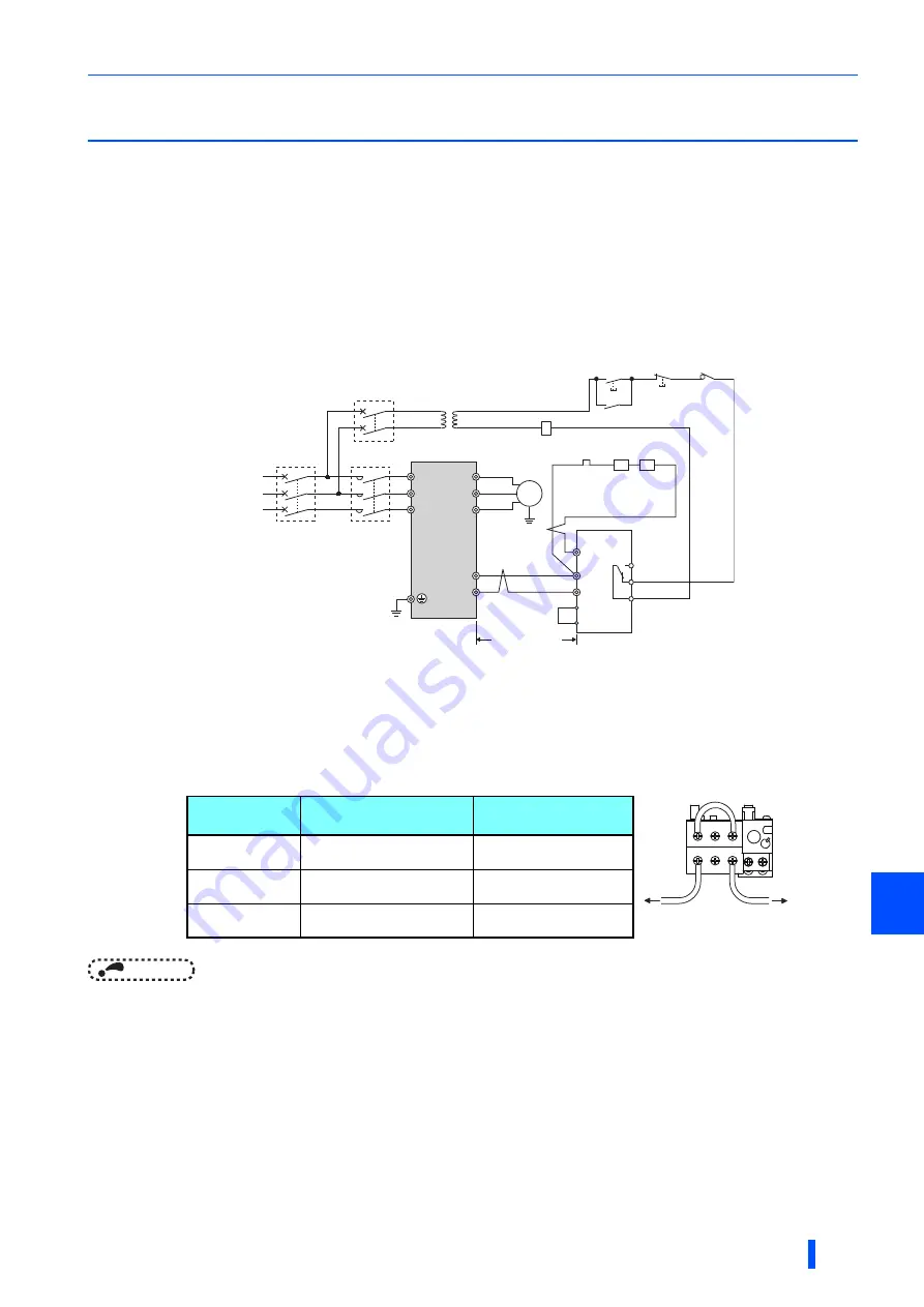
Connect the brake unit (FR-BU2(H)) as shown below to improve the braking capability during deceleration.

Connection example with the GRZG type discharging resistor

NOTE

 • Set "1" in 

Pr.0 Brake mode selection

 of the FR-BU2 to use a GRZG type discharging resistor.

 • Do not remove the jumper across terminals P/+ and P1.



When wiring, make sure to match the terminal symbol (P/+, N/-) at the inverter side and at the brake unit (FR-BU2) side.
(Incorrect connection will damage the inverter and brake unit.)



Install a stepdown transformer.



The wiring distance between the inverter and brake unit (FR-BU2), and between the brake unit (FR-BU2) and 
discharging resistor must be within 5 m. Even when the wires are twisted, the cable length must be within 10 m.



It is recommended to install an external thermal relay to prevent overheat of the discharging resistor.



For the connection method of the discharging resistor, refer to the Instruction Manual of the FR-BU2.

 • Recommended external thermal relay

∗4

∗1

∗3

∗5

U
V

W

P/+

N/-

R/L1
S/L2
T/L3

Motor

M

Inverter

PR

N/-
BUE
SD

P/+

A
B
C

FR-BU2

GRZG type

discharging 

resistor

R

R

Three-phase AC
power supply

MCCB

MC

OFF

ON

MC

10 m or less

OCR 

contact

MC

External thermal
relay

OCR

∗2

∗1

∗3

Brake unit

Discharging resistor

Recommended 

external thermal relay

FR-BU2-H7.5K

GRZG 200-10


(six in series)

TH-T25-3.6A

FR-BU2-H15K

GRZG 300-5


(eight in series)

TH-T25-6.6A

FR-BU2-H30K

GRZG 400-2


(twelve in series)

TH-T25-11A

To a resistor

1/L

1

5/L

3

2/T

1

6/T

3

To the brake
unit terminal P/+

Summary of Contents for FR-F800-E

Page 1: ...ECAUTIONS FOR MAINTENANCE AND INSPECTION 5 SPECIFICATIONS 6 HEAD OFFICE TOKYO BUILDING 2 7 3 MARUNOUCHI CHIYODA KU TOKYO 100 8310 JAPAN IB NA 0600767ENG C 2203 MEE Printed in Japan Specifications subject to change without notice FR F800 E FR F806 E IP55 ULType 12 SPECIFICATIONS INSTRUCTION MANUAL HARDWARE FR F846 00023 0 75K to 03610 160K E L2 Inverter for fans and pumps ...

Page 2: ...ny person who is involved in wiring or inspection shall wait for at least 10 minutes after the power supply has been switched OFF and check that there are no residual voltage using a tester or the like The capacitor is charged with high voltage for some time after power OFF and it is dangerous This inverter must be earthed grounded Earthing grounding must conform to the requirements of national an...

Page 3: ...onsider a 3 reduction in the rated current per 500 m increase in altitude If halogens including fluorine chlorine bromine and iodine contained in fumigants for wood packages enter this product the product may be damaged Prevent the entry of fumigant residuals or use an alternative method such as heat disinfection Note that sterilization or disinfection of wood packages should be performed before p...

Page 4: ...etry operation automatic reset and restart is repeated even if a fault occurs which may damage or burn the inverter the converter unit or the motor Before restarting the normal operation after the operation using the emergency drive function make sure that the inverter the converter unit and the motor have no fault Emergency stop A safety backup such as an emergency brake must be provided for devi...

Page 5: ...labels to the inverter if the retry function and or automatic restart after instantaneous power failure have been enabled For the retry function For automatic restart after instantaneous power failure Application of motor control labels Apply the following labels to the inverter to avoid connecting motors not intended for a particular motor control setting ...

Page 6: ...t 36 2 6 1 Details on the control circuit terminals 36 2 6 2 Control logic sink source change 41 2 6 3 Wiring of control circuit 43 2 6 4 Wiring precautions 46 2 6 5 When supplying 24 V external power to the control circuit 47 2 6 6 Safety stop function 48 2 7 Operation panel FR LU08 01 50 2 7 1 Components of the operation panel 50 2 7 2 Outline of the Main monitor indicator 51 2 7 3 Basic operati...

Page 7: ...tion 78 3 6 Checklist before starting operation 79 3 7 Failsafe system which uses the inverter 81 4 PROTECTIVE FUNCTIONS 83 4 1 Inverter fault and alarm indications 84 4 2 Reset method for the protective functions 84 4 3 Faults history and the list of fault displays 85 4 4 Causes and corrective actions 86 5 PRECAUTIONS FOR MAINTENANCE AND INSPECTION 87 5 1 Inspection item 88 5 1 1 Daily inspection...

Page 8: ...ter outline dimension drawings 121 APPENDIX 125 Appendix 1 Differences and compatibility with the FR F840 126 Appendix 2 Instructions for compliance with the EU Directives 127 Appendix 3 Instructions for UL and cUL 131 Appendix 4 Instructions for EAC 133 Appendix 5 Restricted Use of Hazardous Substances in Electronic and Electrical Products 134 Appendix6 Referenced Standard Requirement of Chinese ...

Page 9: ...MEMO 8 ...

Page 10: ...ter unit External operation Operation using the control circuit signals Combined operation Combined operation using the PU operation panel parameter unit and External operation Mitsubishi Electric standard motor SF JR Mitsubishi Electric constant torque motor SF HRCA Trademarks Company and product names herein are the trademarks and registered trademarks of their respective owners Notes on descrip...

Page 11: ...ink logic 60 Hz 9999 same as the power supply voltage CA terminal CA equipped model Terminal CA analog current output 0 to 20 mADC Terminal AM analog voltage output 0 to 10 VDC ON Source logic 50 Hz 8888 95 of the power supply voltage Rating plate example The SERIAL consists of one symbol two characters indicating the production year and month and six characters indicating the control number The l...

Page 12: ...p Stays ON while the power is supplied to the main circuit 28 k Ethernet communication connector Connect the Ethernet dedicated cable for connection to the network 54 l Main circuit terminal block Connects cables for the main circuit 28 m Wiring cover Remove the protective bushes to connect cables FR F846 00470 22K or lower 18 n Front cover Remove this cover for the installation of the product ins...

Page 13: ...llowing table Name Manual number FR F800 Instruction Manual Detailed IB 0600547ENG Ethernet Function Manual IB 0600628ENG FR Configurator 2 Instruction Manual IB 0600516ENG PLC function programming manual IB 0600492ENG FR LU08 01 Instruction Manual IB 0600539ENG Safety stop function instruction manual BCN A23228 001 ...

Page 14: ...pment 2 1 Peripheral devices 14 2 2 Removal and reinstallation of the front cover 18 2 3 Installation of the inverter 21 2 4 Terminal connection diagrams 24 2 5 Main circuit terminals 28 2 6 Control circuit 36 2 7 Operation panel FR LU08 01 50 2 8 Communication connectors and terminals 53 2 9 Connection of stand alone option units 57 2 10 Installing a communication option 66 ...

Page 15: ...filter ferrite core FR BSF01 FR BLF U V W Earth Ground n Induction motor o Contactor Example No fuse switch DSN type p PM motor MM CF d Magnetic contactor MC a Inverter b Three phase AC power supply Personal computer FR Configurator 2 USB host A connector Communication status indicator LED USB host USB device Mini B connector USB e AC reactor FR HAL P P PR PR f High power factor converter FR HC2 h...

Page 16: ...the molded case circuit breaker Electromagnetic wave interference The input output main circuit of the inverter includes high frequency components which may interfere with the communication devices such as AM radios used near the inverter In this case activating the EMC filter may minimize interference Refer to page 72 For details of options and peripheral devices refer to the respective Instructi...

Page 17: ...er supply system 1000 kVA or more Under such condition the inverter may be damaged if you do not use a reactor Select a reactor according to the applied motor capacity 76 f High power factor converter FR HC2 Suppresses the power supply harmonics significantly Install this as required 61 g Multifunction regeneration converter FR XC Provides a large braking capability Install this as required 62 h P...

Page 18: ...S T21 18 5 FR F846 00380 18 5K 60 A S T35 22 FR F846 00470 22K 75 A S T35 30 FR F846 00620 30K 100 A S T50 37 FR F846 00770 37K 100 A S T50 45 FR F846 00930 45K 125 A S T65 55 FR F846 01160 55K 150 A S T100 75 FR F846 01800 75K 200 A S T100 90 FR F846 02160 90K 225 A S N150 110 FR F846 02600 110K 225 A S N180 132 FR F846 03250 132K 350 A S N220 160 FR F846 03610 160K 400 A S N300 Assumes the use o...

Page 19: ...moved Tighten the front cover installation screws in the numerical order in the figure shown below Inverter Screw type Screw size Screwdriver size FR F846 00470 22K or lower Hexalobular screw M4 T20 FR F846 00620 30K or higher M5 T25 Inverter Tightening torque FR F846 00470 22K or lower 1 4 to 1 9 N m FR F846 00620 30K or higher 2 8 to 3 6 N m FR F846 00023 0 75K to 00170 7 5K FR F846 00620 30K to...

Page 20: ... FR F846 01800 75K or higher Fix the covers with the installation screws To install the front cover for control circuit inspection and or the front cover for main circuit inspection tighten the installation screws in the numerical order in the figure shown below Front cover Screw type Screw size Screwdriver size For control circuit inspection Hexalobular screw M5 T25 For main circuit inspection Fr...

Page 21: ...flange sections Otherwise the front cover may fall off resulting in damage or injuries Before installing the front cover check the waterproof gasket to make sure that it is not damaged If it is damaged contact the nearest Mitsubishi Electric FA center Securely install the front cover to fit the waterproof gasket closely Do not let the waterproof gasket get stuck between the front cover edge and th...

Page 22: ...iderably shorten the service lives of the semiconductors parts capacitors and others Take the following measures to keep the ambient temperature of the inverter within the specified range a Measures against high temperature Ventilate the room Install the inverter in an air conditioned electric chamber Block direct sunlight Provide a shield or similar plate to avoid direct exposure to the radiated ...

Page 23: ...rmeasure Purge air Pump clean air from outside to make the in enclosure air pressure higher than the outside air pressure Corrosive gas salt damage If the inverter is exposed to corrosive gas or to salt near a beach the printed board patterns and parts will corrode or the relays and switches will result in poor contact In such a place take the countermeasures described in Dust dirt oil mist above ...

Page 24: ... heat dissipation space When designing or building an enclosure for the inverter carefully consider influencing factors such as heat generation of the contained devices and the operating environment For the FR F846 00126 5 5K or lower allow 1 cm or more clearance Installation orientation of the inverter Install the inverter on a wall as specified Do not mount it horizontally or in any other way Ab...

Page 25: ...ignal output 0 to 10VDC Earth Ground AM 5 DC0 to 5V selectable DC0 to 10V Multi speed selection Open collector output 6 Moving coil type 1mA full scale Contact input common Calibration resistor 8 Main circuit terminal Control circuit terminal DC0 to 5V DC0 to 10V selectable MC Main circuit C2 B2 A2 Relay output 2 Relay output 5 M DC0 to 20mA DC0 to 5V DC0 to 10V selectable DC4 to 20mA PU connector...

Page 26: ...tor output by setting Pr 291 Not required when calibrating the scale with the operation panel Do not change the initially set ON enabled position of the EMC filter ON OFF connector in the case of the inverter The Class C2 compatibility condition is not satisfied with the EMC filter OFF The FR F846 00250 11K L2 to FR F846 00470 22K L2 are not provided with the EMC filter ON OFF connector The EMC fi...

Page 27: ...DC0 to 5V selectable DC0 to 10V DC0 to 10V Multi speed selection Open collector output 6 Contact input common Main circuit terminal Control circuit terminal DC0 to 5V DC0 to 10V selectable MC Main circuit C2 B2 A2 Relay output 2 Relay output 5 M DC0 to 20mA DC0 to 5V DC0 to 10V selectable DC4 to 20mA PU connector USB A connector USB mini B connector SINK SOURCE 2 3 3 3 3 Connector for plug in opti...

Page 28: ...Manual Detailed Do not change the initially set ON enabled position of the EMC filter ON OFF connector in the case of the inverter The Class C2 compatibility condition is not satisfied with the EMC filter OFF The FR F846 00250 11K L2 to FR F846 00470 22K L2 are not provided with the EMC filter ON OFF connector The EMC filter is always ON The option connector 2 cannot be used because the Ethernet b...

Page 29: ...nect these terminals to a three phase squirrel cage motor or a PM motor P N Brake unit connection Connect the brake unit FR BU2 FR BU BU power regeneration common converter FR CV power regeneration converter MT RC high power factor converter FR HC2 multifunction regeneration converter FR XC or DC power supply under DC feeding mode 57 P P1 Do not remove the jumper across terminals P and P1 except f...

Page 30: ... INSTALLATION AND WIRING 29 2 FR F846 00620 30K to FR F846 01160 55K FR F846 01800 75K to FR F846 03610 160K M R L1S L2 T L3 N P Motor Power supply Jumper Charge lamp Motor Power supply M R L1S L2 T L3 P Jumper Charge lamp N ...

Page 31: ...FR F846 00470 22K or lower remove the protective bushes from the wiring cover For the FR F846 00620 30K to FR F846 01160 55K remove the protective bushes from the bottom of the inverter For the FR F846 01800 75K or higher remove the protective bushes from the bottom and the side of the inverter Do not remove the protective bushes from the holes that are not used for wiring of cables NOTE For the F...

Page 32: ... to the diameter of the holes For the details such as hole diameters and recommended cable glands refer to the following table a a a a c b d a b c d a a a FR F846 00250 11K to 00470 22K FR F846 00023 0 75K to 00170 7 5K FR F846 00620 30K to 01160 55K a b c d a a a FR F846 01800 75K to 03610 160K b c d a a a a ...

Page 33: ...SKINTOP MS SC M20 53112630 SKINTOP MS M20 53112020 SKINDICHT SM M32 52103020 b AC power input wiring 40 4 SKINTOP MS SC M40 53112660 SKINTOP MS M40 BRUSH 53112678 SKINTOP MS M40 53112050 SKINDICHT SM M40 52103050 c Brake unit connection wiring d Inverter output wiring FR F846 00620 30K to 02600 110K a Control circuit wiring 20 3 SKINTOP MS SC M20 53112630 SKINTOP MS M20 53112020 SKINDICHT SM M20 5...

Page 34: ...erature of 90 C XLPE cable It assumes a surrounding air temperature of 40 C or lower Selection example for use mainly in Europe The terminal screw size indicates the size of terminal screw for R L1 S L2 T L3 U V W P N P1 and the screw for earthing grounding The line voltage drop can be calculated by the following formula Line voltage drop V Use a larger diameter cable when the wiring distance is l...

Page 35: ...t operation or even to an inverter failure It may also cause a malfunction or fault of the equipment connected ON the inverter output side Stray capacitance of the wiring differ by the installation condition use the total wiring length in the table above as reference values If the fast response current limit function malfunctions disable this function Refer to Pr 156 Stall prevention operation sel...

Page 36: ...connected with the other equipment at an earthing grounding point Do not use the other equipment s earthing grounding cable to earth ground the inverter as shown in III A leakage current containing many high frequency components flows into the earthing grounding cables of the inverter and peripheral devices Because of this the inverter must be earthed grounded separately from EMI sensitive devices...

Page 37: ...minal JOG is also used as a pulse train input terminal To use as a pulse train input terminal change the Pr 291 setting maximum input pulse 100k pulses s Input resistance 2 k When contacts are short circuited 8 to 13 mADC RT Second function selection Turn ON the RT signal to enable the second function When the second function such as second torque boost and second V F base frequency is set turning...

Page 38: ...s input Input resistance 245 5 Permissible maximum current 30 mA 4 5 Frequency setting current Inputting 4 to 20 mADC or 0 to 5 V 0 to 10 V provides the maximum output frequency at 20 mA and makes input and output proportional This input signal is valid only when the AU signal is ON terminal 2 input is invalid Use Pr 267 to switch among input 4 to 20 mA initial setting 0 to 5 VDC and 0 to 10 VDC S...

Page 39: ...s output Refer to the FR F800 Instruction Manual Detailed OL SE Overload warning Switched to LOW when stall prevention is activated by the stall prevention function Switched to HIGH when stall prevention is canceled IPF SE Instantaneous power failure Switched to LOW when an instantaneous power failure occurs or when the undervoltage protection is activated FU SE Frequency detection Switched to LOW...

Page 40: ...f the output becomes in HIGH state even though both terminals S1 and S2 are open Contact your sales representative for this manual Permissible load 24 VDC 27 VDC at maximum 0 1 A The voltage drop is 3 4 V at maximum while the signal is ON Terminal symbol Common Terminal name Terminal function description Rated specification SD Contact input common sink Common terminal for the contact input termina...

Page 41: ...f interfaces available 1 IP version IPv4 RS 485 PU connector With the PU connector communication can be made through RS 485 For connection on a 1 1 basis only Conforming standard EIA 485 RS 485 Transmission format Multidrop link Communication speed 4800 to 115200 bps Wiring length 500 m USB USB A connector A connector receptacle A USB memory device enables parameter copies and the trace function I...

Page 42: ...of the desired control logic The control logic of input signals is initially set to the sink logic SINK for the FM type The control logic of input signals is initially set to the source logic SOURCE for the CA type The output signals may be used in either the sink or source logic independently of the jumper connector position NOTE Make sure that the jumper connector is installed correctly Never ch...

Page 43: ... inverter due to undesirable currents Source logic Use terminal SD as a common terminal and perform wiring as shown below Do not connect terminal PC of the inverter with the terminal 24 V of the external power supply When using terminals PC SD as a 24 VDC power supply do not install an external power supply in parallel with the inverter Doing so may cause a malfunction in the inverter due to undes...

Page 44: ...g sure that 0 to 0 5 mm of the wire protrudes from the end of the sleeve Check the condition of the crimp terminal after crimping Do not use a crimp terminal of which the crimping is inappropriate or the face is damaged Crimp terminals commercially available as of October 2020 Phoenix Contact Co Ltd A ferrule terminal with an insulation sleeve compatible with the MTW wire which has a thick wire in...

Page 45: ...nded wires without a crimp terminal push the open close button all the way down with a flathead screwdriver and insert the wire Pull the wire while pushing the open close button all the way down firmly with a flathead screwdriver NOTE Pulling out the wire forcefully without pushing the open close button all the way down may damage the terminal block Use a small flathead screwdriver tip thickness 0...

Page 46: ...RL JOG RT MRS RES AU CS The open collector circuit is isolated from the internal control circuit by photocoupler Terminal 5 is a common terminal for the frequency setting terminals 2 1 or 4 and the analog output terminals AM CA It should be protected from external noise using a shielded or twisted cable Terminal SE is a common terminal for the open collector output terminals RUN SU OL IPF FU The c...

Page 47: ... cables connected to the control circuit terminals connect their shields to the common terminal of the connected control circuit terminal When connecting an external power supply to terminal PC however connect the shield of the power supply cable to the negative side of the external power supply Do not directly earth ground the shield to the enclosure etc Always apply a voltage to the fault output...

Page 48: ...e main circuit power supply is OFF the inverter operation is disabled In the initial setting when the main power supply is turned ON during the 24 V external power supply operation a reset is performed in the inverter then the power supply changes to the main circuit power supply The reset can be disabled using Pr 30 For the details of Pr 30 refer to the FR F800 Instruction Manual Detailed Confirm...

Page 49: ...rter wiring near the power supply The increase of the current causes voltage to drop further When connecting different inverters to different power supplies use the inverters after confirming that the input voltage of each inverter is within the rated input voltage range Depending on the power supply the overcurrent protection may be activated and disable the power supply Select the power supply a...

Page 50: ...nal has not been certified for compliance with safety standards For more details refer to the Safety stop function instruction manual A PDF copy can be found in the enclosed CD ROM For how to use this CD ROM refer to page 139 Input power Internal safety circuit status Input terminal Output terminal Output signal Inverter running status Operation panel indication S1 S2 So SO SAFE E SAF SA OFF OFF O...

Page 51: ...tion commands Reset the inverter when the protective function is activated f Setting dial Used to change the frequency and parameter settings Shows the details of the fault when the dial is pressed in the faults history mode g HAND AUTO key Switches the operation mode between HAND PU HANDJOG PUJOG and AUTO External h MON key Displays the first priority monitor For the details refer to the Instruct...

Page 52: ... e Tuning status Displays the offline auto tuning status of the inverter TUNE During turning or tuning completed TUNE highlighted and flickering Tuning error f USB connection password locked Displays the connection status of the USB A connector of the inverter and password function setting status USB A USB connection recognized USB A highlighted USB ready USB A flickering During USB operation LOCK...

Page 53: ...TOP AUTO V Output voltage 1 2 3 4 0 0 PREV SET NEXT STOP AUTO AUTO External operation mode At power ON First monitor At power ON HAND PU operation mode HANDJOG PUJOG operation mode Second monitor Third monitor Value change Example Frequency setting is completed Flicker Parameter setting mode Present setting Value change Example Parameter write is completed Flicker Quick menu Faults history monitor...

Page 54: ...the user side Keep the total cable length within 20 m Commercially available products as of February 2015 Communication operation Using the PU connector enables communication operation from a personal computer etc When the PU connector is connected with a personal FA or other computer by a communication cable a user program can run to monitor the inverter or read and write parameters Communication...

Page 55: ...ommunication specifications Connection cable Use Ethernet cables compliant with the following standards Hub Use a hub that supports transmission speed of the Ethernet Item Description Category 100BASE TX 10BASE T Data transmission speed 100 Mbps 100BASE TX 10 Mbps 10BASE T Transmission method Baseband Maximum segment length 100 m between the hub and the inverter Number of cascade connection stages...

Page 56: ...ng data copied in the USB memory device can be copied to other inverters This function is useful in backing up the parameter setting or for sharing the parameter setting among multiple inverters The parameter setting file can be copied onto a personal computer from the USB memory device and edited using FR Configurator 2 Trace The monitored data and output status of the signals can be saved in a U...

Page 57: ...B hub the inverter cannot recognize the USB memory device properly For the details of the usage of the USB connector refer to the FR F800 Instruction Manual Detailed USB device communication The inverter can be connected to a personal computer with a USB Ver 1 1 cable Parameter setting and monitoring can be performed by FR Configurator 2 NOTE For the details of FR Configurator 2 refer to the Instr...

Page 58: ...ill damage the inverter and brake unit Install a stepdown transformer The wiring distance between the inverter and brake unit FR BU2 and between the brake unit FR BU2 and discharging resistor must be within 5 m Even when the wires are twisted the cable length must be within 10 m It is recommended to install an external thermal relay to prevent overheat of the discharging resistor For the connectio...

Page 59: ...s are twisted the cable length must be within 10 m The contact between TH1 and TH2 is closed in the normal status and is open at a fault When wiring make sure to match the terminal symbol P N at the inverter side and at the brake unit FR BU2 side Incorrect connection will damage the inverter and brake unit Install a stepdown transformer The wiring distance between the inverter and brake unit FR BU...

Page 60: ...that shut off the current in case of a fault Do not remove the jumper across terminals P and P1 When wiring make sure to match the terminal symbol P N at the inverter side and at the brake unit FR BU H side Incorrect connection will damage the inverter Install a stepdown transformer The wiring distance between the inverter and brake unit FR BU and between the brake unit FR BU and resistor unit FR ...

Page 61: ...t BU type and between the brake unit BU type and discharging resistor must be within 2 m Even when the cable is twisted the wiring length must be within 5 m If the transistors in the brake unit should becomes faulty the resistor will overheat and result in a fire Install a magnetic contactor on the inverter s input side and configure a circuit that shut off the current in case of a fault Remove th...

Page 62: ...ion selection to assign the terminals used for the X10 X11 signal For RS 485 or any other communication where the start command is only transmitted once use the X11 signal to save the operation mode at the time of an instantaneous power failure Assign the IPF signal to an FR HC2 terminal Refer to the Instruction Manual of FR HC2 Always connect the FR HC2 terminal RDY to a terminal where the X10 si...

Page 63: ... SW2 If the switch setting does not match the actual wiring the connection mode fault E T occurs After making sure that the wiring is correct and secure set 2 or 102 in Pr 30 Regenerative function selection Power supply MCCB MC FR XCL N FR XC R L1 S L2 T L3 RSO SE C B A RYB IM P P4 R2 L12 S2 L22 T2 L32 R2 L12 S2 L22 T2 L32 P Fuse R L1 N Inverter M S L2 T L3 Fuse RES SD X10 MRS IM R L1 N Inverter M...

Page 64: ...nals R L1 S L2 and T L3 on the inverter Incorrect connection will damage the inverter and the converter Remove the jumper across terminals P and P1 Connect between the inverter terminal P and the converter terminal P and between the inverter terminal N and the converter terminal N for polarity consistency Connecting opposite polarity of terminals P and N will damage the converter and the inverter ...

Page 65: ...Incorrect connection will damage the inverter E OPT option fault will occur Remove the jumper across terminals P and P1 Do not insert an MCCB between terminals P and N between terminals P L and P or between N L and N Connecting the opposite polarity of terminals N and P will damage the inverter Use Pr 178 to Pr 189 input terminal function selection to assign the terminals used for the X10 signal B...

Page 66: ...MT RC install a magnetic contactor MC at the input side of the inverter so that power is supplied to the inverter after 1 second or more has elapsed after powering ON the MT RC When power is supplied to the inverter prior to the MT RC the inverter and the MT RC may be damaged or the MCCB may trip or be damaged When connecting the power coordination reactor and others refer to Instruction Manual of...

Page 67: ...he option as far as it goes Insert it to the inverter option connector 1 3 Remove the mounting screw lower of the Ethernet board earth plate Fit the one terminal of the earthing grounding cable on the Ethernet board earth plate and fix it securely to the inverter with the mounting screw tightening torque 0 33 N m to 0 40 N m 4 Fix the left part of the communication option securely with the option ...

Page 68: ...ns before using the equipment 3 1 Electro magnetic interference EMI and leakage currents 68 3 2 Power supply harmonics 73 3 3 Installation of a reactor 76 3 4 Power OFF and magnetic contactor MC 77 3 5 Countermeasures against deterioration of the 400 V class motor insulation 78 3 6 Checklist before starting operation 79 3 7 Failsafe system which uses the inverter 81 ...

Page 69: ...ith the carrier frequency kept high with low noise To earth ground leakage currents Take caution as long wiring will increase the leakage current Decreasing the carrier frequency of the inverter reduces the leakage current Increasing the motor capacity increases the leakage current Line to line leakage currents Harmonics of leakage currents flowing in static capacitance between the inverter output...

Page 70: ...e used in the earthed neutral system Breaker designed for harmonic and surge suppression Rated sensitivity current I n 10 Ig1 Ign Igi Ig2 Igm Standard breaker Rated sensitivity current I n 10 Ig1 Ign Igi 3 Ig2 Igm Ig1 Ig2 Leakage currents in wire path during commercial power supply operation Ign Leakage current of inverter input side noise filter Igm Leakage current of motor during commercial powe...

Page 71: ...the power cables I O cables and signal cables of the inverter in parallel with each other and do not bundle them Use shielded twisted pair cables for the detector connecting and control signal cables and connect the sheathes of the shielded cables to terminal SD Ground Earth the inverter motor etc at one point Techniques to reduce electromagnetic noises that enter and cause a malfunction of the in...

Page 72: ...easures must be taken Install easily affected devices as far away as possible from the inverter Run easily affected signal cables as far away as possible from the inverter and its I O cables Do not run the signal cables and power cables inverter I O cables in parallel with each other and do not bundle them Use shielded cables as signal cables and power cables and run them in individual metal condu...

Page 73: ...tting NOTE Do not change the initially set ON enabled position of the EMC filter ON OFF connector The Class C2 compatibility condition is not satisfied with the EMC filter OFF The FR F846 00250 11K L2 to FR F846 00470 22K L2 are not provided with the EMC filter ON OFF connector The EMC filter is always ON Warning While power is ON or when the inverter is running do not open the front cover Otherwi...

Page 74: ...r and surge suppressor on the inverter output side may be overheated or damaged by the harmonic components of the inverter output Also since an excessive current flows in the inverter to activate overcurrent protection do not provide a capacitor and surge suppressor on the inverter output side when the motor is driven by the inverter For power factor improvement install a reactor on the inverter i...

Page 75: ...o as the Specific Consumer Guidelines Specific Consumer Guidelines This guideline sets forth the maximum harmonic currents outgoing from a high voltage or especially high voltage receiving consumer who will install add or renew harmonic generating equipment If any of the maximum values is exceeded this guideline requires that consumer to take certain suppression measures Maximum Values of Outgoing...

Page 76: ...rd 25th 0 4 0 81 49 0 57 14 7 6 37 4 116 2 45 2 303 1 568 1 47 1 078 0 75 1 37 83 0 97 24 9 10 79 6 972 4 15 3 901 2 656 2 49 1 826 1 5 2 75 167 1 95 50 1 21 71 14 03 8 35 7 849 5 344 5 01 3 674 2 2 3 96 240 2 81 72 31 20 20 16 12 11 28 7 68 7 2 5 28 3 7 6 50 394 4 61 118 2 51 22 33 10 19 7 18 52 12 61 11 82 8 67 5 5 9 55 579 6 77 173 7 75 27 48 64 28 95 27 21 18 53 17 37 12 74 7 5 12 8 776 9 07 2...

Page 77: ...cantly Connect it to the DC area of an inverter Use the high power factor converter FR HC2 with the accessories that come as standard To use the FR XC series converter use the converter with an FR XCB box type reactor and enable the harmonic suppression function 3 Installation of power factor improving capacitor When used with a reactor connected in series the power factor improving correction cap...

Page 78: ...ting overcurrent protection of the inverter and such will activate When an MC is provided to switch to a commercial power supply for example it is recommended to use the commercial power supply inverter switchover function Pr 135 to Pr 139 Refer to the FR F800 Instruction Manual Detailed The commercial power supply operation is not available with PM motors Handling of the manual contactor on the i...

Page 79: ...verter driven dedicated motor Set Pr 72 PWM frequency selection as indicated below according to the wiring length Suppressing the surge voltage on the inverter side For the FR F846 01160 55K or lower connect the surge voltage suppression filter FR ASF H FR BMF H to the output side For the FR F846 01800 75K or higher connect the sine wave filter MT BSL BSC to the output side Countermeasures for PM ...

Page 80: ...hutting off the power supply For some time after the power OFF a high voltage remains in the smoothing capacitor and it is dangerous Before performing an inspection or rewiring wait 10 minutes or longer after the power supply turns OFF then confirm that the voltage across the main circuit terminals P and N of the inverter is low enough using a tester etc The inverter s output side has no short cir...

Page 81: ...le when changing the motor speed with analog signals the following countermeasures are effective Do not run the signal cables and power cables inverter I O cables in parallel with each other and do not bundle them Run signal cables as far away as possible from power cables inverter I O cables Use shielded cables Install a ferrite core on the signal cable Example ZCAT3035 1330 by TDK 70 A counterme...

Page 82: ...nal Output current detection Y12 signal a Checking by the output of the inverter fault signal When the inverter s protective function activates and the inverter trips the Fault ALM signal is output The ALM signal is assigned to terminal A1B1C1 in the initial setting With this signal check that the inverter operates properly In addition negative logic can be set ON when the inverter is normal OFF w...

Page 83: ...check configure a sequence considering the inverter s deceleration time In addition it is recommended to check the three phase current when using the current detector b Command speed and actual operation check Check for a gap between the actual speed and commanded speed by comparing the inverter s speed command and the speed detected by the speed detector d Checking the motor operating status by t...

Page 84: ...TIVE FUNCTIONS that operates in this product Always read the instructions before using the equipment 4 1 Inverter fault and alarm indications 84 4 2 Reset method for the protective functions 84 4 3 Faults history and the list of fault displays 85 4 4 Causes and corrective actions 86 ...

Page 85: ...ting the inverter fault Resetting an inverter fault with the start signal ON restarts the motor suddenly Item Description Fault output signal Opening the magnetic contactor MC provided on the input side of the inverter at a fault occurrence shuts off the control power to the inverter therefore the fault output will not be retained Fault or alarm indication When a protective function activates the ...

Page 86: ...rload trip electronic thermal relay function E THM Motor overload trip electronic thermal relay function E FIN Heat sink overheat E IPF Instantaneous power failure E UVT Undervoltage E ILF Input phase loss E OLT Stall prevention stop E GF Output side earth ground fault overcurrent E SOT Loss of synchronism detection E LUP Upper limit fault detection E LDN Lower limit fault detection E LF Output ph...

Page 87: ...rective action The fan may be faulty Please contact your sales representative Operation panel indication Abnormal Intnl Temp Name Abnormal internal temperature Description The inverter trips when the inverter internal temperature reaches the specified value or higher Check point Check for too high surrounding air temperature Check if the internal air circulation fan or the cooling fan stops due to...

Page 88: ...S FOR MAINTENANCE AND INSPECTION This chapter explains the PRECAUTIONS FOR MAINTENANCE AND INSPECTION for this product Always read the instructions before using the equipment 5 1 Inspection item 88 5 2 Measurement of main circuit voltages currents and powers 113 ...

Page 89: ...eriodic inspection Check and clean the cooling system Clean the air filter etc Check the tightening and retighten The screws and bolts may become loose due to vibration temperature changes etc Check and tighten them Tighten them according to the specified tightening torque Refer to page 33 Check the conductors and insulating materials for corrosion and damage Measure the insulation resistance Chec...

Page 90: ...manufacturer Smoothing aluminum electrolytic capacitor 1 Check for liquid leakage Contact the manufacturer 2 Check for safety valve projection and bulge Contact the manufacturer 3 Visual check and judge by the life check of the main circuit capacitor Refer to page 92 Relay contactor Check that the operation is normal and no chattering sound is heard Contact the manufacturer Resistor 1 Check for cr...

Page 91: ...facturer Load motor Operation check Check for vibration and abnormal increase in operation noise Stop the equipment and contact the manufacturer Waterproof performance dustproof performance Operation panel 1 Check that it is installed Install it securely Refer to page 54 2 Check for deformation or fracture Stop the equipment and contact the manufacturer 3 Check for loose fixing screws Retighten Fr...

Page 92: ...numbers and terminals to be checked Assumes the use of an analog meter 5 1 5 Cleaning Always run the inverter in a clean status When cleaning the inverter gently wipe dirty areas with a soft cloth immersed in neutral detergent or ethanol NOTE Do not use solvent such as acetone benzene toluene and alcohol as these will cause the inverter surface paint to peel off The display etc of the operation pa...

Page 93: ...er parts The inverter diagnoses the main circuit capacitor control circuit capacitor cooling fan internal fan and inrush current limit circuit by itself and estimates their lives The self diagnostic warning is output when the life span of each part is near its end It gives an indication of replacement time The life warning output can be used as a guideline for life judgment NOTE Refer to the FR F8...

Page 94: ... confirming the function of each terminal For replacement of each part contact the nearest Mitsubishi Electric FA center Replacement procedure of the fan The replacement interval of the cooling fan used for cooling the parts generating heat such as the main circuit semiconductor is greatly affected by the ambient temperature When unusual noise and or vibration are noticed during inspection the coo...

Page 95: ...val of the cooling fan FR F846 00620 30K to 01160 55K 1 Remove the installation screws and then remove the fan cover 2 Disconnect the fan connectors 3 Remove the installation screws and then remove the fan Installation screw Fan cover Fan connector Installation screw ...

Page 96: ...oval of the cooling fan FR F846 01800 75K to 03610 160K 1 Remove the installation screws and then remove the fan cover 2 Disconnect the fan connectors 3 Remove the installation screws and then remove the fan Fan cover Installation screw Fan connector Installation screw ...

Page 97: ...allation screws tightening torque 1 4 to 1 9 N m 2 Route the fan lead through the clamp and then reconnect the fan connectors 3 Attach the fan cover with the installation screws tightening torque 1 4 to 1 9 N m NOTE Installing the fan in the opposite direction of air flow can cause the inverter life to be shorter Prevent the cable from being caught when installing a fan AIR FLOW Fan side Installat...

Page 98: ...tallation screws tightening torque 1 4 to 1 9 N m 2 Route the fan lead through the clamp and then reconnect the fan connectors 3 Attach the fan cover with the installation screws tightening torque 1 4 to 1 9 N m NOTE Installing the fan in the opposite direction of air flow can cause the inverter life to be shorter Prevent the cable from being caught when installing a fan AIR FLOW Fan side Installa...

Page 99: ...ix the fan with the installation screws tightening torque 1 4 to 1 9 N m 2 Reconnect the fan connectors 3 Attach the fan cover with the installation screws tightening torque 1 4 to 1 9 N m NOTE Installing the fan in the opposite direction of air flow can cause the inverter life to be shorter Prevent the cable from being caught when installing a fan AIR FLOW Fan side Installation screw Fan connecto...

Page 100: ... 1 Remove the inverter front cover Refer to page 18 2 Move the fan connector case and then remove the fan connector 3 Remove the installation screws and then remove the bracket 4 Remove the installation screws and then remove the fan Fan connector Connector case Bracket Installation screw Bracket Fan Installation screw ...

Page 101: ... front cover Refer to page 18 2 Remove the installation screws and then remove the protective cover 3 Move the fan connector case and then remove the fan connector 4 Remove the bracket 5 Remove the installation screws and then remove the fan Installation screw Protective cover Fan connector Connector case Bracket Bracket Fan Installation screw ...

Page 102: ...nal fan FR F846 00620 30K to 01160 55K 1 Remove the inverter front cover Refer to page 18 2 Move the fan connector case and then remove the fan connector 3 Remove the installation screws and the bracket and then remove the fan Fan connector Connector case Bracket Fan Installation screw ...

Page 103: ...n screws and then remove the fan Removal of the internal fan lower FR F846 01800 75K to 02600 110K 1 Remove the inverter front cover Refer to page 18 2 Move the fan connector case and then remove the fan connector 3 Remove the installation screws and then remove the bracket 4 Remove the installation screws and then remove the fan Fan connector Connector case Fan Installation screw Fan connector Co...

Page 104: ...he installation screws and then remove the fan Removal of the internal fan lower FR F846 03250 132K or higher 1 Remove the inverter front cover Refer to page 18 2 Move the fan connector case and then remove the fan connector 3 Remove the installation screws and then remove the bracket 4 Remove the installation screws and then remove the fan Fan connector Connector case Bracket Installation screw I...

Page 105: ...ghtening torque 1 4 to 1 9 N m 2 Fix the bracket to the inverter with the installation screws tightening torque 1 4 to 1 9 N m 3 Reconnect the fan connector and then place the connector case from the above 4 Reinstall the inverter front cover Refer to page 18 NOTE Installing the fan in the opposite direction of air flow can cause the inverter life to be shorter Prevent the cable from being caught ...

Page 106: ...erter 3 Reconnect the fan connector and then place the connector case from the above 4 Fix the protective cover with the installation screws tightening torque 1 4 to 1 9 N m 5 Reinstall the inverter front cover Refer to page 18 NOTE Installing the fan in the opposite direction of air flow can cause the inverter life to be shorter Prevent the cable from being caught when installing a fan The wiring...

Page 107: ... The AIR FLOW arrow on the fan side indicates the air flow direction 2 Reconnect the fan connector and then place the connector case from the above 3 Reinstall the inverter front cover Refer to page 18 NOTE Installing the fan in the opposite direction of air flow can cause the inverter life to be shorter Prevent the cable from being caught when installing a fan AIR FLOW Fan side Installation screw...

Page 108: ...elow The AIR FLOW arrow on the fan side indicates the air flow direction 2 Reconnect the fan connector and then place the connector case from the above 3 Reinstall the inverter front cover Refer to page 18 NOTE Installing the fan in the opposite direction of air flow can cause the inverter life to be shorter Prevent the cable from being caught when installing a fan AIR FLOW Fan side Fan Installati...

Page 109: ...de indicates the air flow direction 2 Attach the bracket to the inverter 3 Reconnect the fan connector and then place the connector case from the above 4 Reinstall the inverter front cover Refer to page 18 NOTE Installing the fan in the opposite direction of air flow can cause the inverter life to be shorter Prevent the cable from being caught when installing a fan AIR FLOW Fan side Bracket Fan In...

Page 110: ...de indicates the air flow direction 2 Attach the bracket to the inverter 3 Reconnect the fan connector and then place the connector case from the above 4 Reinstall the inverter front cover Refer to page 18 NOTE Installing the fan in the opposite direction of air flow can cause the inverter life to be shorter Prevent the cable from being caught when installing a fan AIR FLOW Fan side Installation s...

Page 111: ...aluminum electrolytic capacitor is used for stabilizing the control power in the control circuit Adverse effects from ripple currents deteriorate capacitors Replacement intervals of capacitors vary greatly with surrounding temperatures and operating conditions Replace them roughly every 10 years when used in normal air conditioned environments Inspecting the product visually Case Check that the si...

Page 112: ...put signals Refer to page 41 5 1 7 Removal and reinstallation of the control circuit terminal block This product has a removable control circuit terminal block which can be replaced with a new one or a control terminal option Removal and reinstallation 1 Loosen the two installation screws at the both side of the control circuit terminal block These screws cannot be removed Slide down the control c...

Page 113: ...to the inverter and the pins on the inverter control circuit connector are not bent After checking proper connection fix the terminal block in place with two screws NOTE Do not tilt the terminal block while tightening the screws or removing it from the inverter Otherwise a stress applied to the control circuit terminal block or the control circuit connector may cause damage to them After replacing...

Page 114: ...n the next page NOTE When installing meters etc on the inverter output side When the inverter to motor wiring length is large especially small capacity models the meters and CTs may generate heat due to line to line leakage current Therefore choose the equipment which has enough allowance for the current rating To measure and display the output voltage and output current of the inverter it is reco...

Page 115: ...the phases is 10 or lower of the inverter rated current Output side power P2 U V W and across U and V V and W P2 W21 W22 2 wattmeter method or 3 wattmeter method Output side power factor Pf2 Calculate in similar manner to power supply side power factor Converter output Across P and N Digital multimeter or other tester Inverter LED is lit 1 35 V1 Frequency setting signal Across 2 4 and 5 Digital mu...

Page 116: ...2 5 Measurement of converter output voltage across terminals P and N The output voltage of the converter is output across terminals P and N and can be measured with a voltmeter such as a digital multimeter Although the voltage varies according to the power supply voltage approximately 540 VDC to 600 VDC is output when no load is connected and voltage decreases during driving load operation When en...

Page 117: ...ntrol circuit Use a 500 VDC megger NOTE Before performing the insulation resistance test on the external circuit disconnect the cables from all terminals of the inverter so that the test voltage is not applied to the inverter For the continuity test of the control circuit use a tester high resistance range and do not use the megger or buzzer 5 2 8 Pressure test Do not conduct a pressure test Deter...

Page 118: ...SPECIFICATIONS This chapter explains the SPECIFICATIONS of this product Always read the instructions before using the equipment 6 1 Inverter rating 118 6 2 Common specifications 119 6 3 Inverter outline dimension drawings 121 ...

Page 119: ...truction Manual Detailed UL Type 12 Enclosure Suitable for Installation in a Compartment Handling Conditioned Air Plenum For compliance with IP55 remove the protective bushes and install the recommended cable glands Model FR F846 00023 0 75K 00038 1 5K 00052 2 2K 00083 3 7K 00126 5 5K 00170 7 5K 00250 11K 00310 15K 00380 18 5K 00470 22K 00620 30K 00770 37K 00930 45K 01160 55K 01800 75K 02160 90K 0...

Page 120: ...peration selection stop selection deceleration stop coasting power failure deceleration stop function PLC function life diagnosis maintenance timer current average monitor multiple rating test run 24 V power supply input for control circuit safety stop function self power management BACnet communication PID gain tuning cleaning load characteristics storage emergency drive Output signal Open collec...

Page 121: ...ing Surrounding air humidity With circuit board coating conforming to IEC60721 3 3 1994 3C2 3S2 95 RH or less non condensing Without circuit board coating 90 RH or less non condensing Storage temperature 20 C to 65 C Atmosphere Indoors without corrosive gas flammable gas oil mist dust and dirt etc Altitude vibration Maximum 2500 m for the installation at an altitude above 1 000 m derate the rated ...

Page 122: ...1 6 6 3 Inverter outline dimension drawings FR F846 00023 0 75K to 00170 7 5K FR F846 00250 11K to 00470 22K Unit mm Unit mm 520 238 271 2 3 508 5 201 18 5 8 7 18 5 2 8 hole 650 238 285 23 610 20 2 3 632 5 8 5 201 18 5 10 20 9 18 5 2 10 hole 4 20 hole FAN ...

Page 123: ...03610 160K Unit mm Unit mm 345 10 300 22 5 12 22 5 10 790 770 357 24 754 18 2 3 18 FAN 2 12 hole 4 25 hole 420 35 175 175 35 15 10 H1 H2 H 2 3 456 6 23 H3 23 24 3 15 hole 4 25 hole FAN Inverter Model H H1 H2 H3 FR F846 01800 75K to 02600 110K 1360 1334 16 1314 FR F846 03250 132K 03610 160K 1510 1482 18 1464 ...

Page 124: ... Operation panel FR LU08 01 NOTE The FR LU08 01 cannot be installed on enclosure surfaces For the outline dimensions of the dedicated motors refer to the FR F800 Instruction Manual Detailed Unit mm 19 80 0 5 3 5 0 3 96 5 0 5 89 5 0 3 68 0 5 5 0 3 15 3 0 0 5 ...

Page 125: ...MEMO 124 ...

Page 126: ...ompliance with the EU Directives 127 Appendix 3 Instructions for UL and cUL 131 Appendix 4 Instructions for EAC 133 Appendix 5 Restricted Use of Hazardous Substances in Electronic and Electrical Products 134 Appendix 6 Referenced Standard Requirement of Chinese standardized law 135 Appendix 7 Compliance with the UK certification scheme 135 Appendix 8 Compliance with the EU ErP Directive Ecodesign ...

Page 127: ...ection Setting range 0 to 2 10 11 20 21 100 to 102 110 111 120 121 Setting range 0 2 10 20 100 102 110 120 Pr 71 Applied motor Setting range 0 to 6 13 to 16 20 23 24 40 43 44 50 53 54 70 73 74 210 213 214 240 243 244 8090 8093 8094 9090 9093 9094 Setting range 0 to 6 13 to 16 20 23 24 40 43 44 50 53 54 70 73 74 8090 8093 8094 9090 9093 9094 Pr 998 PM parameter initialization Setting range 0 12 14 ...

Page 128: ...pe B V Address Mitsubishi Electric Platz 1 40882 Ratingen Germany EMC Directive We declare that this inverter conforms with the EMC Directive and affix the CE marking on the inverter EMC Directive 2014 30 EU Standard s EN 61800 3 2004 A1 2012 First environment PDS Category C2 Second environment PDS Category C3 The applicable standard depends on the type of the built in EMC filter Please ensure you...

Page 129: ... is connected only to a supply with a short circuit power Ssc greater than or equal to the value mentioned in the table below If the equipment input current is more than 75 A and the power supply capacity is 100 kVA or more limits for the harmonic current emissions of IEC61000 3 4 shall apply However the equipment complies with IEC61000 3 4 provided that the short circuit ratio Rsce is greater tha...

Page 130: ...ower specified in IEC60664 On the input and output of the inverter and the converter unit use cables of the size and type set forth in EN 60204 1 or IEC 60364 5 52 The operating capacity of the relay outputs terminal symbols A1 B1 C1 A2 B2 C2 should be 30VDC 0 3A Relay output has basic isolation from the inverter internal circuit Control circuit terminals on page 24 are safely isolated from the ma...

Page 131: ...e compliant to the EU RoHS Directive 2011 65 EU and affix the CE marking on the inverters Operation characteristics of electronic thermal relay function This function detects the overload of the motor stops the operation of the inverter s output transistor and stops the output The operation characteristic is shown on the left When using the Mitsubishi Electric constant torque motor 1 Set one of 1 ...

Page 132: ...T Class J or Class CC fuse or UL 489 Molded Case Circuit Breaker MCCB must be provided in accordance with the Canadian Electrical Code and any applicable local codes Maximum allowable rating by the US National Electrical Code Exact size must be chosen for each installation Select an appropriate molded case circuit breaker with a rating that is suitable for the size of the cable Wiring to the power...

Page 133: ... overheat of the motor stops the operation of the inverter s output transistor and stops the output The operation characteristic is shown on the left When using the Mitsubishi Electric constant torque motor 1 Set one of 1 13 to 16 50 53 54 in Pr 71 This provides a 100 continuous torque characteristic in the low speed range 2 Set the rated current of the motor in Pr 9 When a value 50 of the inverte...

Page 134: ...l Regulations CU TR and the EAC marking must be affixed to the products For information on the country of origin manufacture year and month and authorized sales representative importer in the CU area of this product refer to the following Country of origin indication Check the rating plate of the product Refer to page 10 Example MADE IN JAPAN Manufactured year and month Check the SERIAL number ind...

Page 135: ...n of the Use of Hazardous Substances in Electrical and Electronic Products of the People s Republic of China 电器电子产品有害物质限制使用标识要求 本产品中所含有的有害物质的名称 含量 含有部件如下表所示 产品中所含有害物质的名称及含量 上表依据 SJ T11364 的规定编制 表示该有害物质在该部件所有均质材料中的含量均在 GB T26572 规定的限量要求以下 表示该有害物质在该部件的至少一种均质材料中的含量超出 GB T26572 规定的限量要求 即使表中记载为 根据产品型号 也可能会有有害物质的含量为限制值以下的情况 根据产品型号 一部分部件可能不包含在产品中 环境保护使 用期限标识 部件名称 有害物质 铅 Pb 汞 Hg 镉 Cd 六价铬 Cr VI 多溴联苯 PBB 多溴...

Page 136: ... meets the listed standards Appendix 7 Compliance with the UK certification scheme We declare that this product conforms with the related technical requirements under UK legislation and affix the UKCA UK Conformity Assessed marking on the product Approval conditions are the same as those for the EU Directives Refer to page 127 UKCA marking The UKCA marking is used for products sold in the markets ...

Page 137: ... 1 1 6 1 6 1 6 1 4 1 4 IE2 FR F846 00126 5 5K 8 8 22 0 2 1 2 1 2 1 1 4 1 4 1 4 1 2 1 2 IE2 FR F846 00170 7 5K 12 27 0 1 8 1 8 1 8 1 3 1 3 1 3 1 1 1 1 IE2 FR F846 00250 11K 18 27 0 1 9 1 9 1 9 1 0 1 0 1 0 0 8 0 8 IE2 FR F846 00310 15K 22 28 5 1 9 1 9 1 9 1 0 1 0 1 0 0 8 0 8 IE2 FR F846 00380 18 5K 27 28 5 1 8 1 8 1 8 1 0 1 0 1 0 0 8 0 8 IE2 FR F846 00470 22K 33 28 5 1 6 1 6 1 6 0 9 0 9 0 9 0 7 0 7 ...

Page 138: ...e cause with a scientific technology that was not available at the time of the shipment of the Product from our company any other failures which we are not responsible for or which you acknowledge we are not responsible for 2 Term of warranty after the stop of production 1 We may accept the repair at charge for another seven 7 years after the production of the product is discontinued The announcem...

Page 139: ...MEMO 138 ...

Page 140: ...ects in the enclosed CD ROM and related documents NOTE This is a personal computer dedicated CD ROM Do not attempt to play it on ordinary audio devices The loud volume may damage hearing and speakers System requirements for the enclosed CD ROM The following system is required to read instruction manuals contained in the enclosed CD ROM Operating method of the enclosed CD ROM How to read instructio...

Page 141: ...evision Aug 2017 IB NA 0600767ENG A First edition Nov 2017 IB NA 0600767ENG B Added Safety stop function Mar 2022 IB NA 0600767ENG C Added Instructions for compliance with the EU Directives Compliance with the UK certification scheme Compliance with the EU ErP Directive Ecodesign Directive IB NA 0600767ENG C ...

Page 142: ...on Terminals S1 and S2 can be selected as digital sources for the trace function Select the digital sources input output signals to be set to Pr 1038 to Pr 1045 from the following table When a value other than the ones in the following table is set 0 OFF is applied for indication Setting value Signal name Setting value Signal name Setting value Signal name 1 STF 21 X0 101 RUN 2 STR 22 X1 102 SU 3 ...

Page 143: ...ECAUTIONS FOR MAINTENANCE AND INSPECTION 5 SPECIFICATIONS 6 HEAD OFFICE TOKYO BUILDING 2 7 3 MARUNOUCHI CHIYODA KU TOKYO 100 8310 JAPAN IB NA 0600767ENG C 2203 MEE Printed in Japan Specifications subject to change without notice FR F800 E FR F806 E IP55 ULType 12 SPECIFICATIONS INSTRUCTION MANUAL HARDWARE FR F846 00023 0 75K to 03610 160K E L2 Inverter for fans and pumps ...

Reviews: