background image

AC

SPINDLE 

T R O U B L E S H O O T I N G


A D V A N C E D  

 EVER 

MITSUBISHI 

USA-E99991-075-*

Summary of Contents for FREQROL-SF

Page 1: ...AC SPINDLE DRIV T R O U B L E S H O O T I N G i i Z ADVANCED AND EVER AOVAkCfNG _ MITSUBISHI ELECTRKZ USA E99991 075 ...

Page 2: ...ipment the equipment normally works 1 3 Checking method and remedy of trouble classification B 1 3 1 1 3 2 1 3 3 1 3 4 1 3 5 1 3 6 1 3 7 1 3 8 I When the power is turned on the display of the operation panel does not appear at all When the power is turned on the display on the operation panel does not indicated the speed in the status display mode as shown in the following figure An alarm appears ...

Page 3: ...acing SF TL card 63 2 4 4 Replacing SF CA card 64 2 5 Checking transistor module This method is the same both in the power side and regeneration side 65 2 6 Checking diode stack 68 2 7 Replacing transistor module and diode stack 70 2 8 Replacing motor cooling 71 2 9 Adjusting and replacing motor built in encoder 74 2 9 1 Adjusting printed circuit board 74 2 9 2 Replacing encoder and printed circui...

Page 4: ...ine Connection 120 Appendix l l Power connection 120 Appendix l 2 Connection with motor for standard motor 122 Appendix l 3 Machine connection 122 without orientation standard Appendix l 4 Machine connection 123 Appendix l 5 Machine connection Bus linkage with NC 124 Magnesensor orientation 1 point specification Appendix l 6 Machine connection Bus linkage with NC 125 with encoder synchronous tap o...

Page 5: ...54 Check Terminals 155 Appendix 10 Parameter Setting List and Short Pin Switch Appendix 11 Structural Components Appendix 12 Maintenance Instruments Reference Setting and Adjustment 1 1 Set switches set pins and variable resistors 1 1 1 SF CA card 1 1 2 SF GR card 1 1 3 SF TL card 1 2 Setting parameters 1 2 1 Display and set switches on SF CA card 1 2 2 Setting parameters from spindle amplifier 1 ...

Page 6: ...select and use test apparatus When installing any test apparatus on a portion to be tested take care not to touch any portion being grounded Generally when conducting a test do not ground the case of any test apparatus Thus because a high voltage may be applied between the test apparatus case and the ground when operating the equipment while adjusting repairing it take care of it o While the power...

Page 7: ... it occurs Does the trouble or fault differ between the forward rotation and reverse rotation Is there an instantaneous power failure Does the trouble or fault occur when a special opera tion or instruction is executed How often does the trouble or fault occur At what load situation does the trouble or fault occurs Whether a load is applied or removed Is a suspicious part replaced with a new one o...

Page 8: ...uipment does not work in occasions The orientation stop position deviates from 3 the specific position Although an alarm 1 2 3 lights it is recovered by turning off and then on the equipment or by resetting it When the power is turned on the display of 1 the operation panel does not appear at all Alternatevely the DC voltage of the printed 1 3 1 circuit board is not correct When the power is turne...

Page 9: ... The motor vibrates with a large noise during rotations 1 3 6 8 The motor overshoots at speed or hunts 1 3 7 B 9 The cutting force degrades 1 3 8 10 The orientation of the spindle is not correctly 1 3 g performed 11 The acceleration deceleration time becomes 1 3 10 lonq 12 The speed detection signal up to speed signal 1 3 11 or zero speed signal is not issued 13 The tapping work is not correctly p...

Page 10: ...EFERENCE 7 The following table lists the contents of the four types of status display modes Item Code SPEED I REFERENCE 1 SPEED 1 POSITION DROOP 1 LOAD L SPEED R E F E R E N C E _ I INPUT Unit Description rpm Represents the motor speed rpm Pulse rpm Represents the motor reference speed Represents remaining pulses on the deviation counter In the case of reverse side pulse negative number the decima...

Page 11: ...e ready MM__ I II state I Sequence 1 Represents the non ready 0 Check the contents of the external signal 1 CTMl and external signal 2 CTM2 of input signals and external signal 3 STSl and external signal 4 STS2 of output signals by comparing them with the following table Note On the NC spindle monitor display ALM DGN3 the external signal 1 and external signal 4 are checked as a control input and c...

Page 12: ...ntents of signals by each digit of LED using the following table selectselect b External signal 2 CTM2 Check the signal contents by each digit of LED using the following table 2 1 10 J1 n LED SVON RDY Digit Servo Ready O N ON 0 1 k J 3 j I_ ...

Page 13: ...1 Troubleshooting 1 1 Status display and diagnosis c External signal 3 STSl Check the signal contents by each digit of LED using the following table 1 0 f Servo Ready ON ON 8 ...

Page 14: ...C EMERGENCY STOP Warning which is issued when the power voltage temporarily drops cl i y 12vJr Lp A c_ A Warning which is issued when a parameter value exceeds the allow able range OWarning which is issued when an emergency stop signal is inputted from the CNC in bus linkage with the M300 series CNC owarning which is issued when an emergency stop signal is inputted from the outside while the exter...

Page 15: ...defective when the alarm No 37 PE parameter error occurs Note 1 If a multiple of parameters is defective check and correct the parameters in accordance with the parameter error Nos until the alarm No 37 does not occur Note 2 An example of display is as follows 19 l l I I I Indicating parameter Am D l error No Status display and diagnosis Pressing the E which is one of function selection keys and t...

Page 16: ...motor speed Motor speed The unit is in rpm Represents a ratio of load against the rating MOTOR RATE output The unit is 8 The 30 minute rating output is 100 The motor rate is in the range 0 to 120 Represents the contents of alarms which occurred in the spindle amplifier this time and last time ALARM NO with code numbers However the last alarm is Spindle alarm the smallest number alarm which differs...

Page 17: ...Display D O Description Represents a control output being outputted from the spindle amplifier corresponding to bits D O H 7 6543210 D O L 7 6 5 4 3 2 10 12 ...

Page 18: ... or more until tht command of the forward rotation signal reverse rotation signal or orientation signal is received after the ready ON state BWhen both the forward rotation signal and reverse rotation signal are turned on at a time the motor does not rotate it becomes the DC exciting state BWhen the forward rotation signa or reverse rotation signal is inputted when the speed refere nce is 0 the mo...

Page 19: ... 1 Check and readjust the spindle orientation control circuyt by referencing Chapter 7 Check the cause and take the proper remedy by referencing Section 1 3 3 which describes the contents of alarms An alarm appears on 11 the NC CRT screen 0 Check the cause and take the proper remedy by referencing Section 1 1 2 which describes the status display and diag nosis The LED3 red on the 12 amplifier ligh...

Page 20: ...rotation signals See Section 1 1 1 2 The input signal from 0 Check each bit of a control 0 Conduct the same counter the NC is abnormal input by referencing Section measures as the Item 3 above 1 1 2 which describes the 4 status display and diagnosis 0 At the same time check the same items as the Item 3 above The signal from the 0 Set the parameter of the 0 Adjust the related control encoder which ...

Page 21: ...t the backlash becomes Note This trouble small often occurs when o Check the backlash between orientation is in the spindle encoder and correctly conducted spindle The equipment malfunc o Check the voltage waveform o Place a serge killer near tions with a too large of the amplifier input pins the noise source noise Xl x2 and X3 with an For example 200 VAC Power supply line oscilloscope DCR 2 12003...

Page 22: ...inside 0 Disconnect the connectors D Replace the printed circuit the printed circuit which are connected between board SF CA card with a new board SF CA card is the SF CA card and SF PW one 4 shortcircuited module CON21 to CON24 turn See Section 2 4 4 on the power again and check that the indication lamp LED1 lights The control power SF PW o Check that 200 VAC power is o Replace the control power ...

Page 23: ...e NC NC is turned on the display nectars CNlA and CNlB through the bus the bus on the operation panel is as cable connectors CNlA follows and CNlB on the printed 3 circuit board SF TL card I i are not correctly con nected D Check the position of the rotary switch CSl on the SF TL card by referencing Refer ence 1 1 3 See Appendix 6t31 1 When the equipment is o Even after the power of the o Correctl...

Page 24: ...er countermeasures by follows referencing the description 7 relating to alarm display I_ I 3 7 Section 1 3 3 on display of the amplifier and Section 1 3 4 On NC CRT The transmission of o Even after the power of the o Check that the rotary switch parameters is required NC is turned on the display CSl on the SF TL card is on the operation panel is as placed in thecorrectposition follows 0 Check that...

Page 25: ...s of the alarm which appears on the spindle amplifier are the same as those which appear on the NC CRT The contents of alarms are listed in the following table The details of each alarm are described in the following Note If the alarm No 12 MEl memory error 1 occurs it should be reset by turning off the power of the spindle amplifier On the other hand other alarm Nos should be reset by turning off...

Page 26: ...signal is not input from the orientation en SPINDLE ENS coder or the signal is not in the correct level A 22 NSS IC MAC012 ERROR The part IC MAC012 on the controlling printed circuit board does not correctly works A SPEED CONTROL ERROR The difference between the referenced speed and 23 OSE EXCESS motor speed is 50 rpm or more and it takes for A 12 set or more 24 BRT B L j a I fli current which exc...

Page 27: ...abnormal or the main circuit devices are overheated because an over A load is applied or the air cooling fan stops The motor is overheated because an overload is applied or the motor cooling blower stops lowing error exceeds the sbecific value In the bus linkage with the M300 series CNC any fault occurs in an other servo axis A Any function which is not provided with the option card is selected A ...

Page 28: ... while the spindle motor is in the acceleration deceleration state or while an overload is applied o Increase the power capacity 0 Check that the voltage bet ween ACDOW and DO24 of the block A in the SF PW module is 5V See Appendix 6 4 o Replace the SF PW module with a new one The control power SF PW module is defec tive 2 Alarm No l20l Zll Memory Error 1 The integrify of the contents Of ROM are c...

Page 29: ...one The ground wires of the o Visually check that the NC amplifier and motor ground wires are correctly are not correctly con connected by referencing nected Appendix 1 o Correclty connect the ground wires 6 L The signal cable is not correclty shielded The printed circuit board SF TL card is defective_ The NC side printed circuit board 611 or MC632 is defective 0 Visually check that the signal cab...

Page 30: ...le off the NF in the unit is o To check only the control turned off circuit without appearance of alarm No 17 set the 2 parameter X58 CVHS to 1 However to return back to the normal operation mode make sure to set the 158 CVHS to 0 Otherwise the LED1 which lights dur ing regeneration on the SF CA card continuously lights 5 Alarm No 20 NSl IC MAC007 Error The internal codes of the IC MAC007 on the S...

Page 31: ...o Check the wave form in the D Replace the encoder with the spindle orientation is same manner as Item 1 above new one defective 2 o Replace the encoder with a new one and check that the equipment correctly works See Appendix 7 The printed circuit o Observe the signal waveform o Replace the printed circuit board SF TL card is from the encoder at CONB board SF TL card with a 3 defective on the SF T...

Page 32: ...when the bit 8 of the parameter OSR2 is 0 the same waveform as the above figure occurs 7 Alarm No 22 NSS IC MAC012 Error The internal codes of the IC MAC012 are checked 1 Item Cause Check Remedy The IC MAC 012 and o Replace the SF CA card with a o Replace the printed circuit the related circuits on new one and check that the board SF CA card with the 1 the printed circuit equipment correctly works...

Page 33: ... is defective D Replace the SF CA card with a o Replace the printed circuit new one and check that the board SF CA card with the equipment correctly works new one See Chapter 2 The integration gain D Check the parameters being o Set the parameters to the parameter VKI amplifier set by referencing Section standard values by refer parameter X37 NC para 1 1 1 or 1 1 2 encing Reference 1 2 2 or meter ...

Page 34: ... same manner as the Item 6 check the signal waveform of the check pins on the SF CA card using an oscilloscope 7 0 By referencing the descrip tion relating to adjustment and replacement of the motor built in encoder described in Section 2 9 observe the waveforms between PA and PGA and between PB and PGA using an oscilloscope and check that they can be in the standard value range using volume resis...

Page 35: ...power impedance is low that two transformers speed 2 are connected in series 0 Tighten the screws of con or a variable auto 0 Check that the input voltage nections between the input transformer is con temporarily drops to 170 V power supply and amplifier netted or less when the motor decelerates The input power fre 0 Check the voltage frequencies 0 Check the cause of the fre quency remarkably at t...

Page 36: ...ee Appendix 9 l 0 Check that the motor is over loaded using a load meter or the load display in the status display mode see Section 1 1 1 3 Visually check the cable con nections 0 Check that the screws of the cable connection terminal are loosen Disconnect the cables between the amplifier and motor and check the insulation resist ance between the following leads Between U and W between V and W bet...

Page 37: ...to gear ratio is in encing Reference 1 2 2 for correctly set that which is set from the Note Compare the parameter 1 amplifier and Reference 1 2 3 in the parameter list on for that which is set from the cover of the amplifier the NC with that being set See Appendix 10 The connector CNlA o Check the cable in the same o Securely connect the connec 2 which is linked with the manner as the alarm No 15...

Page 38: ... and 37 or NC dixes l 4 and l 5 parameters 22 and X23 Note To check the occurrence o If the signal output is b If the alarm does not saturated when it exceeds occur 10 V because a too high speed decrease the parameter is set check that the volt values of VKP and VKI age rises to around 115 in the speed mode of the status display see Section 1 1 1 or using the NC CRT monitor The motor built in en D...

Page 39: ...r 0 Replase the power supply with that whose impedance 2 is low o Tighten the screws of the cable connections between the input power and ampli fier An instantaneous power o In the same manner as the o See the alarm No lO UV failure occurs in the alarm No lO LJV check the o Check the cause of the 3 input voltage or the input power voltage drops when the instantaneous power failure motor decelerate...

Page 40: ...with the NC alarm No lS ME21 check the new one through the bus is connector defective The NC amplifier and o In the same manner as the a Correctly ground them 3 motor are not correctly alarm No l5 ME2 check the grounded grounding The signal cable is not o In the same manner as the o Correctly sheild the signal 4 correctly shielded alarm No lS ME21 check the cable shielding of the signal cable The ...

Page 41: ...e spindle speed reference exceeds 6192 xlOr GRA rpm Parameter GRA number of gear teeth on spindle side o Correct the program 20 Alarm No 37 PE Parameter Error This alarm occurs when a parameter which exceeds the allowable range is set 1 Item Cause Check Remedy 1 I I o Correctly set the parameter value A parameter which exceeds the allowable range is set o Check that the parameter be ing set accord...

Page 42: ...perations o Check that the equipment is frequently started and stopped The thermal protector o Check that electricity o Replace the thermal protec THSZ which is instal does not flow between the tor THSl or THSZ led on the fin is ends of the thermal protec See Section 2 2 defective tor by referencing Appendix Alternatively the 4 Main circuit block dia thermal protector THS1 gramn and Appendix 5 whi...

Page 43: ...or the load display in the status display mode see Section 1 1 1 0 Check that the motor is fre quently started and stopped o After stopping the motor and turning the cooling fan to fully cool the motor check that the motor leads OHS1 and OHS2 is shortcircuited When they are shortcircuited the thermal protector is normal o Check the wire breakage or connector imperfect contact using a circuit teste...

Page 44: ...lifier SMO and OM using an oscillo parameter 33 or NC para 4 scope and check that the meter 19 PR acceleration time is shorter than the reference constant time See Appendixes 1 4 and l 5 24 Alarm No 56 OA Other Axis Fault Item Cause Check Remedy 1 The servo axis alarm o Check that the servo axis o Remove the cause of the occurs alarm occurs servo axis alarm The cable CAM11 which o Replace the cabl...

Page 45: ...larm No 57 OPE Option Card Error Item Cause Check Remedy The option card does D Check that the order list D Check the specification 1 not conform with the conforms with the option card specification name 40 ...

Page 46: ...e the control power 4 SF PW module is defec voltages of the SF PW module supply SF PW module with tive using a circuit tester a new one See Appendix 6 4 See Section 2 4 1 The printed circuit o Set the amplifier parameterer o Replace the printed circuit board SF CA card is as follows input a reference board SF CA card with a new defective amnrrnn Note one See Section 2 4 4 speed in the open loop st...

Page 47: ...are incor rectly set Check o Check that the control power SF PW module is normal and the amplifier display LED does not indicate any mes sage o Check how the PIN1 and PIN2 are set See Reference 1 1 1 4 Remedy I o Correctly set the PIN1 and PIN2 on the SF CA card 42 ...

Page 48: ...Increase the value of the o Correctly set the value of reference is incorrect speed reference and check the external speed refer 4 that the motor speed pro ence portionally increase Between CH46 and AGA of SF CA card The motor built in en o Check the signal waveform by o See the alarm No 23 OSE coder is defective referencing the alarm No 23 5 OSE D Replace the encoder or the printed circuit board ...

Page 49: ... vibrates and gener one ates noise in the Item 1 above The mounting screws o Check that the screws o Securely tighten the screws which fasten the motor flange portion or leg which 3 to the machine are fasten the motor to the loosen machine are loosen in the Item 1 above The reference sine wave 0 Observe that the waveforms o Replase the printed circuit forms of the control are balanced at the follo...

Page 50: ...n control circuit common ground The control circuit common is the OM terminal of the terminal board TBl on the SF CA card c Between main circuit control circuit common between each terminal of the main circuit and OM terminal Note The insulation resist ance should be 20MR or more See Appendixes l l and 6 l 45 ...

Page 51: ... as their standard values respectively 1 o Amplifier parameter No 136 and X37 o NC parameter 22 PRJ 23 PR 9 CRT screen NC parameter 54 PR 55 PR 14 CRT screen See References 1 2 2 and 1 2 3 The speed loop gain is o Set the parameters VKP and 0 Set both the parameters so too high VKI to low values and check that they are nearly the that the motor does not hunt same low values or overshoot 2 0 For th...

Page 52: ...ued TLl or No 21 TL2 is input TLl and TL2 to 2 turned on by referencing release the torque limit Appendix l 4 or l 5 The torque limit para o Check the parameter TLM 0 Correctly set the parameter meter is incorrectly value by referencing Refer value set ence 1 2 2 2 or 1 2 3 3 3 o Amplifier parameter No 35 o NC parameter 21 PR 9 CRT screen NC parameter 53 PR 14 CRT screen 4 The belt is loosen 0 Che...

Page 53: ...et to 1 o On the spindle amplifier dis o Since the cable is defec play check that the external tive replace it with a new signal 1 CTMl bit 6 see one Section 1 1 1 is not set to 1 Q In case of analog connection Connection cable to CON1 In case of bus con 1 nection Connection cable to CNlA CAM111 See Appendixes 1 and 2 o Since the printed circuit board is defective replace it with a new one 0 In ca...

Page 54: ...R or SF TL card Waveform bet gm ween CH2 and OM l L Waveform bet ween CH3 and OM Check that the above wave forms are normal Note The OM terminal is located on the SF CA card terminal board lower right portion See Appendix 6 l See the note of the alarm No 21 Section 3 5 and Appendix 9 2 131 1 The following printed o In the same manner as the D Readjust the related cont circuit board is defec Item 1...

Page 55: ...uit ring is correct 0 Replace the control power SF PW module with a new In the case that power is The side A of the PIN 3 is supplied from the NC The side B of the PIN 3 is shortcircuited on the shortcircuited on the SF OR card SF OR card The portions 2 and 3 of the PIN 5 are shortcircuited on the SF TL card SF OR card or SF TL card one with a new one See Section 5 3 1 S Alternatively replace the ...

Page 56: ...nner as the o Readjust the spindle orien circuit board is defec Item 1 of b above check tation control circuit by tive that the position feedback referencing Section 3 0 In case of analog signal is normal 0 If it is impossible to re linkage adjust such a circuit re 3 SF OR card or place the printed circuit SF CA card board with a new one In case of bus See Section 2 4 2 and linkage 2 4 3 SF TL car...

Page 57: ...ar ratio is incor depends on the gear being ratio are as follows rectly set used GRAl GRAZ GRA3 GRA4 D Check that the servo rigidity GRBl GRBZ GRB3 GRB4 5 is weak o NC parameter 25 PR to 32 PR 9 CRT screen NC parameter 57 PR to 64 PR 14 CRT screen D Spindle parameter 139 and 40 See References 1 2 2 and 1 2 3 1 52 ...

Page 58: ...ix l 4 or 1 5 Remedy o Turn off the limit command input TLl and TL2 to re lease the torque limit The Ea ROM No is o Check the E ROM No by o Replace the ROM with a cor 2 incorrect referencing Appendix 11 rect one or change the Table 1 1 related parameter 3 The parameter 33CSN o Check the parameter by value is too large referencing Reference 1 2 2 o Correctly change the para meter value 53 ...

Page 59: ...the 0 In the same manner as Sec 2 accord with that being Item 1 above check the tion 1 3 5 take the proper specified related signal countermeasures The output circuit of o Check that the external o Replace the SF CA card with the SF CA card is defec signal 4 STSZ bit 2 SD a new one 3 tive speed detection bit 5 See Section 2 4 4 UTS up to speed or bit 4 2s zero speed is turned on The cable which is...

Page 60: ... the 2 high machining program with the S command of the machining speed being set by the program machine manufacturer The spindle orientation o Check that the waveforms at o Replace the detector or encoder or printed cir the check terminals CHl printed circuit board with cuit board SF TL card CH2 and CH3 on the SF TL a new one is defective card are normal See Section 2 4 2 or 3 See the instruction...

Page 61: ...same manner as the check method of the Item 6 of the does not deviate in ac alarm No 23 OSE cordance with the Items 6 7 and 8 of the alarm No 23 OSE i adjust the variable resistor in the motor built in encoder and ii replace the printed circuit board or sensor with a new one The up to speed signal o Check the external signal in o Take proper countermeasures 2 or zero speed signal is the status dis...

Page 62: ... 4 3 card or SF OR card are nor mal The cable between the o In the same manner as the o Replace the cable with a orientation encoder of Item 1 above check the wave new one 2 the spindle and the forms at the check terminals amplifier is defective on the SF TL card or SF OR card The speed of the spindle D In the same manner as the 0 In the same manner as the motor deviates for 10 step 1 of Section 2...

Page 63: ...t 1 1 c of remove the card and store 2 Then remove the E2PROM from the old amplifier or SF CA card and mount it on the new amplifier or SF CA card 3 Last mount the E PROM which was extracted from the new amplifier or SF CA card on the old amplifier or SF CA card How to extract E PROM Arm 0 0 Widen the arms of the ROM extractor in the arrow direction as shown in the left hand figure and insert both...

Page 64: ...nel which houses the printed circuit board SF CA card manually re move white fuses Fl F2 and F3 which are inserted into the control circuit filter FILl on the small panel and replace them with new ones 2 2 Replacing thermal protectors By referencing Appendixes 5 l to 41 unsolder the two leads which are soldered loosen the mounting screws and replace the thermal THSl Fixed on THS2 Fixed on 2 3 Repl...

Page 65: ...c relay RA1 is mounted on the bottom plate loosen the mounting screws and remove the electromagnetic relay from the bottom plate Extract the base plate where the cooling fan is mounted from the amplifier main unit See the following figure Terminal block fixing screw hole Protection bush Cooling fan fixing screw e side where the cooling fan late is not stuck Extract the leads from the protection bu...

Page 66: ...rew A r SF PW Connector Power supply rear side r r r r_ T __ L___J L _ J L____ C a v i t y u SF CA card Screw SF PW Power supply Screw __ 0 II 0 Hinge panel The SF CA card has been removed 1 i By referencing Appendix 2 1 or 2 2 keep the follow ing connectors and cable connections as they are On SF CA card CONl CON2 CON3 TB2 On SF OR card CON4 CONB CONAA CONC On SF OR10 card Or on SF TL card CNlB C...

Page 67: ...nd remove it After replacing the SF PW power supply semble the parts in the reverse order of assembling procedure module as the dis Note When mounting the SF CA card push the connec tor by your fingers from the front side of the card so that the connector on the rear side of the SF CA card is securely connected to the SF CA card 2 4 2 Replacing SF OR or SF OR10 card Connector Rear side 0 1 I i____...

Page 68: ...ing SF TL card Connector Rear side Termination r e s i s t o r y L Screw c3 i By referencing Appendix 2 3 remove the connectors CNlA CONB CONAA and termination resistor CNlB ii Loosen the five screws and remove the SF TL card iii After the SF TL card is replaced assemble the parts being disassembled in the reverse order of the assembling procedure Note When mounting the card by pushing the connec ...

Page 69: ...e five nails on the SF CA card and loosen the two screws iv Raise the SF CA card from the lower side and remove it from the hinge panel Last insert your fingers into the hinge panel cavi ties 2 positions and remove the entire SF CA card from the hinge panel v After the SF CA card is replaced assemble the parts being disassembled in the reverse order of the assem bling procedure Note vi Adjust mete...

Page 70: ...acing the SF CA card first remove the E2ROM from the old card and then mount it on the new card 2 5 Checking transistor module This method is the same both in the power side and regeneration side a 75 A or less b 100 A or more 0 L 1 1 Ii I Iti 2 Note The following figure shows the relationship between the terminal symbols and circuit diagram of the above transistor module Cl 0 T 65 ...

Page 71: ...he following criteria check the electric continuity of each terminal and determine whether the transistor module is good or bad Note Even if part of the transistor module is defec tive replace the entire amplifier with a new one In addition if the transistor module should be replaced to prevent the transistors from being damaged by your static electricity ground yourself and replace it by referenc...

Page 72: ...everal 10R Shortcircuited Between indefinite C2El and E2 G2El 0 terminal Indefinite Shortcircuited several 100R Between C2El terminal Indefinite Shortcircuited several 100 R C2El and G2 C2El 0 terminal Indefinite Shortcircuited several 100 R Between G2 and E2 G2 Q terminal Several 1OOR Shortcircuited indefinite G2 0 terminal Indefinite Shortcircuited several 100 R Between Bl and Cl Bl I terminal I...

Page 73: ...nal symbols and circuit diagram of the above diode stack ii Check the electric continuity of each two terminals in accordance with the criterion list and check that the diode stack is good or no good First check the electric continuity between P and N 1 i Remove the leads which are b h nals P and N connected to the termi 68 ...

Page 74: ...i IllUczLIIIILt nal Shortcircuited S e v e r a l 1022 G_ l_FG_ c_ Between P terminal Indefinite Shortcircuited several 1005 P and T P 0 termi nal Several 10R Shortcircuited indefinite Between N termi nal Several 102 Shortcircuited N and R N 0 termi nal Indefinite Shortcircuited several 10012 Between N and S Between N and T nal Several 109 Shortcircuited indefinite nal Indefinite Shortcircuited sev...

Page 75: ...tening torque see the following table mount the devices in the same direction as the old ones and then connect the leads Note Put on the tube on the terminal G of the tran sis tor module Tightening torque table Maximum Recommended Model Screw size tightening tightening torque torque kg cm PT768 kg cm Diode PD608 M5 x 0 8 20 17 2 PD1008 Tran UM75CDY 10 sis UMlOOCDY 10 M5 x 0 8 20 17 f 2 tor UM150CD...

Page 76: ... Remove the P flat head screw which is located at the center of the cooling fan and only the fan can be dis mounted Cut the four leads of the cooling fan which are connected in the terminal box Remove the P flat head screw which fastens the fan motor main body and the fan motor main unit can be dis mounted from the fan case 71 ...

Page 77: ... 3 Fan Finger guard lb 1 In the case of 160 frames or more Remove the three hex socket bolts which fasten the fan case and pull the fan case in the rear direction and the fan case with the cooling fan can be dismounted 2 Remove the hex socket bolts which fasten the finger guard 72 ...

Page 78: ...g fan which are connected in the terminal box Remove the P flat head screw which fastens the cooling fan from the inside of the fan case and the cool fan can be dismounted from the fan case 4 Assemble the parts in the reverse order of 73 ...

Page 79: ...ut Between PA and PGA Phase B output Between PB and PGA ii Rotate the motor in the forward direction counter clockwise viewed from the shaft end at a low speed so that the waveform can be easily observed and adjust the following four volumes until the follow ing output waveforms can be observed Volumes Adjustment function VRl Zero level adjust ment of chase A VR2 Amplitude adjust ment of phase A T...

Page 80: ...pendix 6 l to reset the equipment to the closed loop Rotate the motor at the maximum speed and check that the amplitudes of the signal outputs for the forward rotation and reverse rotation are 0 8 V or more v Check that the motor speed is the middle speed of the base speed approx 1500 rpm and the envelopes of the signal waveforms of the phases A and B are 0 3 V or less The following figure exempli...

Page 81: ...1 If the printed circuit board is defective If the items for ii to vi cannot be adjusted on the printed circuit board which is mounted on the motor replace the board with a new one and try to adjust the same items Note 2 If the gap between the sensor in the motor and the detection gear is incorrect By referencing Section 4 2 replace the set of sensor and printed circuit board with new ones and try...

Page 82: ...the time take care not to collide the sensor with the detection gear 4 To adjust the sensor position loosen the sensor mounting screw while the sensor mounting plate is fastened and adjust the gap between the detection gear and the sensor using a thickness gauge the gap is marked on the sensor mounting plate At the time check that the sen sor s match mark marking off lines matches that of the moun...

Page 83: ...nd re 2 9 placing motor built in encoder 5 Apply screw lock paint on the sensor mounting screws and plate mounting screws 6 When assembling the fan case fully extend the sensor leads into the terminal box to prevent them from getting caught 78 ...

Page 84: ...ientation control circuit This chapter describes the maintenance installation and adjustment procedures for the electric orientation fixed position stop function which is provided to the spindle of an NC machine 79 ...

Page 85: ...ure 3 1 1 Spindle orientation using magnesensor 1 point a Where speed selection signal function is provided External signal Option card Spindle Controller Option card Sf OK Orientation L y I I c z F Speed selection signal Ul CONC Magne i _ A L__ _ Spindle 1 CON2 I 80 ...

Page 86: ...rough the bus _ Control section Externa signal To last axis CNlA CNlB of MR S Option card S F T L Magnesensor Spindle r Controller Orientation command bit N c rr Option card Orientation position I command data s F I I_ CN A Bus line Magne 1 CON2 81 ...

Page 87: ...____ nn ion card aF OR Orientation command t CON1 Orientation command Controller Option card SF I n CONC position command I 12 bit binary r Ml9 MO6 I R CON2 u I Spindle N C Note When the direction of the motor rotation differs from that of the encoder rotation it is necessary to change the bit 8 and bit E of the parameter 0RS2 amplifier parameter 30 82 ...

Page 88: ... resistor Controller Option card SF TI CN I A Bus line r _ _ Orientation position command data l 71C O N A A L E 1 C O N B 1 N C Spindle n C O N 2 I Note When the direction of the motor rotation differs from that of the encoder rotation it is necessary to change the bit 8 and bit E of the parameter ORS2 amplifier parameter 30 NC parameter 116 PR 83 ...

Page 89: ...rientation Time taken for start of creep speed 0 5OOms after passing over liner zone is set 0 359tdeg I Standard setting 133 Orientation Angle at which creep speed for position 22 PG2 2nd deceler loop starts is set 0 40 deg ation point Standard setting 20 Encoder Magnesensor Positioning range within which orientation complete signal is 1 5760 1 512 Orientation output is set l l6 deg 24 zRz in posi...

Page 90: ... 0 7 2 0 8 3 0 9 4 1 5 1 2 6 1 4 7 1 6 8 1 8 9 2 A 2 2 B 2 4 C 2 6 D 2 8 E 3 F 3 2 Oriented spindle stop Kp magnific ation T 4 bit combina tion times 44it combina tion I rad s I 0 0 6 0 Delay 0 0 55 1 0 7 advance 1 1 1 2 0 8 1 PI 2 1 65 3 0 9 3 2 2 4 1 4 2 75 5 1 2 5 3 3 6 1 4 6 3 85 7 1 6 7 4 4 8 1 8 8 4 95 9 2 9 5 5 A 2 2 A 6 05 B 2 4 B 6 6 C 2 6 c 7 15 D 2 8 D 7 7 E 3 E 8 25 F 3 2 F 8 8 Note Th...

Page 91: ... 1 j Elose with spindle encoder 1 Semiclose without spindle encoder 0 ir 01 PRE Same as previous direction I EMG in position dtput is not held 0 Faint exci 1 In EMG in position tation output is held 1 Intense ex In 31OMT 3lOL T citation it is set to Normally 0 1 1 Z bit combina tion 00 PRE 01 CCW Mckor forward rotation 10 cw Motor reverse rotation 11 Prohibited direction Note The position loop l d...

Page 92: ...e 0 Invalid 1 Valid M 3C hine ready signal in NC mode 0 Invalid 1 Valid he magnification for 21PGl first decel oration point for orientation for respec Live gear is set F 87 0 Cl Gear 01 Gear 00 F 87 0 c2 Gear 11 Gear 10 OH 1601 is regarded as 1 time Set to idjust orientation for the respective rear If 0 is set it becomes 1 time he magnification for Y22PG2 second leceleration point for orientation...

Page 93: ...3 Spindle orientation control circuit 3 2 Control circuit and Darameter settina 2 Check terminals See Appendix g 2 88 ...

Page 94: ...isted in the following No Name Setting Description I Outputs an encoder I I I I IL feedback signal from CONB to CONAA PIN 1 Outputs a feedback sig PIN 2 nal from the CON2 motor IBare board I I detector to CONNA CONNA output I drawing No However the phase Z 52 is not selection outputs the linear zone used of the magnesensor outputs a feedback sig nal from the CON2 motor detector to CONAA J No power...

Page 95: ...t from the amplifier and the other is set from the NC CRT being asterisked The contents of the parameters are the same as those in Section 3 2 1 l For instructions for setting parameters see Reference 1 2 3 The following table lists parameters which are set from the NC CRT 90 ...

Page 96: ... Magnesensor spindle orientation point The time in which creep speed starts after passing through linear zone is set 0 359cdeg J Standard setting 133 Spindle orienta 2 22 PG2 ie d Angle at which creep speed run changes to position control loop is set 0 40tdeg I tion Standard setting 20 point Spindle Encoder Magnesensor orienta The error range within which spindle ori 4 24 ZRZ tion in entation comp...

Page 97: ... stop state is valid from the next orienta tion ST Position shift Magnesensor orientation The stop position is set within range from 5 deg to 5 deg Setting 28 3RC value 2560 512 divi sions n value 2048 512 divi Setting value 1536 When 0 deg is 2048 in the direc tion 2048 n in the direction 2048 n Data during orientation stop can be changed Not used Set to no l Setting range unit Encoder 0 4095 pul...

Page 98: ... 5 1 2 6 1 4 6 1 4 7 1 6 7 1 6 8 1 8 a 1 8 9 2 9 2 A 2 2 A 2 2 B 2 4 B 2 4 c 2 6 C 2 6 D 2 8 D 2 8 E 3 E 3 F 3 2 F 3 2 BjA9876543210 Oriented spindle stop Kp magnific ation UT selec Y tion 4 rad sl 0 6 rn r 4 bit combina tion Irad sl 0 Delay 0 0 55 advance 1 1 1 1 PI 2 1 65 3 2 2 4 2 75 5 3 3 6 3 85 7 4 4 a 4 95 9 5 5 A 6 05 8 6 6 c 7 15 D 7 7 E a 25 F a 8 Note The Kp magnification should be set t...

Page 99: ...se with encoder 1 Semiclose 01 CCw Hotor forward rotation 10 cw Motor reverse rotation 11 Prohibited PPJS same as direction encoder 0 In EMG in Position output is not held 0 Faint exci l In EMG in Position tation output is held 1 Intense ex In 31OMT 31OLT citation it is set to Normally 0 1 1 0 direction Note The position loop l Jdirection means the synchro nous tap O direction 1 direction Position...

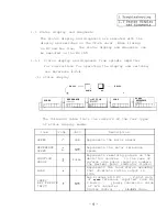
Page 100: ... 3 Display lamps See Appendix 8 2 4 Check terminals See Appendix g 3 95 ...

Page 101: ......

Page 102: ......

Page 103: ......

Page 104: ......

Page 105: ......

Page 106: ......

Page 107: ......

Page 108: ......

Page 109: ......

Page 110: ......

Page 111: ......

Page 112: ...sed Note Note Adjust the stop position point d using the para meter PST If the spindle hunts when the motor is stopped by the orientation operation the selection of the mounting direction of the orientation detector is inverted At the time correct the selection using the parameter ORS2 bit 8 107 ...

Page 113: ...e OSP 220 and PGl 133 not defective are determined 2 Check that the SF OR or SF TL card is defective 3 Check that the mechanical NG system backlash is larqe Decrease PGl min 80 Decrease OSP Note 1 2 When the orientation time is long because the time period point b to c on which the spindle rotates at a creep speed increase OSP and PGl in the man ner that the spindle doesn t overrun when it stops T...

Page 114: ...justment procedure OSP CSP PGl PG2 The spindle overruns when it stops Note 1 Increase the parameter value Do not change the parameter value I Decrease the parameter value Note 2 When the spindle remarkably hunts in the orien tation stop state since the selection of the mounting direction of the orientation detector is reversed correct the selection with the parameter 0RS2 bit 8 109 ...

Page 115: ...t values can be obtained Note PGl Based on point c move point a When decreasing PGl point a approaches point c PG2 Based on point c move point b When decreasing PG2 point b approaches point c In the adjustment using the following flowchart generally a gear where the spindle speed is high tends to overrun so it should be adjusted first In addition with the parameters obtained by the adjustment chec...

Page 116: ...0 are determined OK OSP and PGl are determined OK OSP and PGl are determined Note 1 2 When the orientation time becomes long because the time period on which the spindle rotates at a creep speed point b to c is long decrease PGl or in crease OSP in the manner that the spindle does not overrun when it stops PGl PG2 the maximum value of OSP 300 The parameter ORSl bits 0 to 3 WT selection are the com...

Page 117: ...G2 The spindle overruns when it stops The orientation time is long The spindle hunts when it stops 1 Note 1 Increase the parameter value Do not change the parameter value I Decrease the parameter value Note 2 When the spindle remarkably hunts in the orien tation stop state since the selection of the mounting direction of the orientation detector is reversed correct the selection with the parameter...

Page 118: ...and Up to speed CUTS Slow down I timer PGI Orientation Slow 6own timer PG1 In the case where the rotation direction is reverse from the oriented rotation direction while the orien tation direction is fixed to a specific direction which is selected by a parameter Forward t 4 Reverse u Creep speed Orientation speed 113 ...

Page 119: ...r software timer parameter PGl times out the motor speed is switched from the orientation speed to the creep speed e When the sensor LS signal goes high by the creep speed the position loop becomes valid f The spindle stops under control of the position loop when the sensor MS signal is at 0 V g The orientation complete signal is turned on closed Direction of orientation rotation set by parameter ...

Page 120: ...otor speed reaches the orientation speed the up to speed signal is turned on After the up to speed signal is turned on when a mark pulse is received the counting starts At the time the motor speed remains as the orienta tion speed Before 146 to 225 deg of the target value the orien tation speed is changed to the creep speed Before 15 to 25 deg of the target value the position loop becomes valid an...

Page 121: ...In the orientation stop state even if the machine ready complete signal SETl SET2 are turned off and then turned on the orientation state remains unchanged Note The stop position is controlled by a 12 bit contact signal OlH to 12H and is controlled by the follow ing equation When all signals are turned off open the stop position is at the reference stop position 0 deg Stop position H12 2 Hll 2 Hl ...

Page 122: ...It should be the same as tap ting 15 g of the axis specification axis z Spindle para meter ORS2 bit F Sets the zero return direction before the synchronous tapping bit E Sets the rotation direction of the position loop detector In the semi close state it is 0 bit B __ When it is set to 1 excitation takes place in the position loop state The response increases against the impact load Normally it is...

Page 123: ...AL0521 1 The position loop detection occurs direction of spindle parameter 1 0RS2 bit E is reversed 2 The fundamental specification tap tl is too short The spindle rotating 1 The setting of close semi close traveling amount does of spindle parameter ORS2 bit not conform with that A is incorrect 2 being specified 2 The spindle parameter gear ratio settings GRAl to GRA4 and GRBl to GRB4 are incorrec...

Page 124: ...p magnification 4 3 Notes 1 When the spindle is driven by a belt in the semi close type which does not use a spindle encoder due to slippage of belt it is difficult to perform accurate tapping operation In the case of belt driving type use a spindle encoder and perform the synchronous tapping operation using the spindle encoder 2 When the spindle is connected to the encoder in the ratio of 2 to 1 ...

Page 125: ...r supply I 2 0 200 23OV s 50 ml I 2 I x 00 x 2 00 c 13 I x 3 0 0 E 7A T The power capacity should conform with the specific ation The power cable should conform with the cable size des cribed in Appendix 3 When the length of the power cable is long its size should be large to prevent power fluctuation 120 ...

Page 126: ...hile the machine ready signal is turned on For the main circuit cable size for the motor see Appendix 3 l Main circuit cables The cable for the motor detector should be a twisted pair shield cable whose length is 20 m or less Ground a cable which connects the motor ground and controller ground 121 ...

Page 127: ...tput signal up to speed output signal Open col lec tar 80 pen col lec 1ete Emergency stop input Alarm reset input Machine ready Speed detection output signal complete input command Input command input Spindle fault output signal alarm signal Load detectionoutput signal Speed detection output srgnal up to speed output signal zero speed output srgnal Torque limit output srqnal Orientation complete o...

Page 128: ......

Page 129: ......

Page 130: ......

Page 131: ......

Page 132: ......

Page 133: ......

Page 134: ......

Page 135: ......

Page 136: ......

Page 137: ......

Page 138: ......

Page 139: ......

Page 140: ......

Page 141: ......

Page 142: ......

Page 143: ......

Page 144: ......

Page 145: ......

Page 146: ......

Page 147: ......

Page 148: ......

Page 149: ......

Page 150: ... 2 SF OR card Note The setting pin names of the bare board drawing number G51 differ from those of G52 Number in parentheses are pin number of G52 Example Sl Name for G51 PINl Name for G52 145 ...

Page 151: ... board drawing G51 part layout 2 Bare board drawing G52 part layout r 1 I CONII I 0 i___________J I P IJI I 2 i c7 E I INi g 0 PIN4 l CI11 c s1 ggj l CI12 CN I B l 113 c 4 1 2 3 loool PIN5 C N I A I I C O N B C O N A A 146 ...

Page 152: ...to 253V input 4 1 1 IEI AC200 AC0 Note 1 2 The blocks B C D E F G H and I are power supplies for the base amplifier of the main cir cuit power transistors_ Note that they are not insulated from the main circuit The 0 V lines of the block A DGA AGA D024 are mutually connected 147 ...

Page 153: ...ked by the machine manufacturer 7 T I 1 1te1 N o 1 Part name I l Capacity Model name Maker kW WY 1 rt class Selection s Ird ZceEZ jOry Code CBl Remarks r 1 3 9 3 6 1 3 4 0 0 0 0 0 0 0 zl E 0 0 0 0 0 0 0 ii I I I 5 5 NF50CS 7 5 3P 11 o fuse breaker NGlOOCS 3P 0 TRR TRS TRT TRRl 3 T l 3 TRTl 3 3 0 9 0 3 5 5 UM75CDY 10 7 5 1 UMlOOCDY 10 TRU TRV TRW 0 11 H UM150CDY 10 15 I TRUl Z TRVl Z TRW1 2 DI Dl 1...

Page 154: ...43 11 H19 15 Electrolytic 18 5 3200UFX350V condenser 22 BKO NC1043 26 H20 Nippon Chemicon 3 4 0 0 Nippon condenser Cl l 5 1 SK50 AC200V Electro magnetic contactor SK65 AC200V MC1 0 Mitsu bishi 26 N3951MVL FAN1 FAN1 FAN2 Cooling fan w Tobishi Kosan 7 H ACL 1 CZ R S l c3 u v v 6 I 11 I CZ R S I 3 co 4C reactor 5 5 HO2 7 5 HO3 11 HO4 15 HO5 18 5 BKO HO6 22 NC6321 HO7 26 HO7 Chuo Denki 0 0 Sizuki 149 ...

Page 155: ... 0 0 0 fi r c 3 6 3 6 3 1 2 1 1 1 r 10 11 12 13 surge absorber BKO C1916HOl 3 0 C2 Rl Tl C2 Rl c2 Sl C2 Tl Rl R2 R3 6 0 SHIZUKI Micron Denki 5 5 HO2 7 5 HO3 11 HO4 15 HO5 18 5 BKO HO6 22 NC1120 HO7 26 HO7 iesistor 5 5 7 5 RO MFS30A802K Micron RO 1 Denki RO 2 OMRON iesistor 2 5 5 G453342 26 TDC24V 14 ielay 15 Relay 16 Thermal protector RAl 1 5 5 G451142 26 TDC24V 1 1 cc OMRON RA2 5 5 Tohoku 26 OHD ...

Page 156: ...20 KOSHIN 4 0 TE K14 3 5 5 TE K22B 3 Terminal board Mitsu bishi TB3 Mitsu TB4 bishi TBll TE K60B 3 26 I Terminal 5 5 board 26 TE K2 3 Noise filter Fuse 21 SHIZUKI FILl 1 0 BKO NC6143HOl MFCONR SA S Fl F2 F3 rub 2 fus1 h c rasl g qent zontainec Toyo Fuse 22 23 24 25 3 3 DCR2 12003 5041 Matsuo Electric Surge killer 5 5 26 SK1 SF PW SF CA Module 5 5 26 t Yamabishi Electric BKO NC6233 Mitsu bishi SF C...

Page 157: ... F O R Mitsu bishi 1 0 S F O R S F T L l kc 1 0 Mitsu bishi Sony Magne scale 1 0 Magnet Yagnesensor option BKO C1810H02 Sensor 0 Sony Magne scale BKO C1810HOl Ampli fier I Sony Magne scale Encoder RFH1024 22 option lM 68 TAMAGAWA Motor built in encoder TS1860N14 TAMAGAWA 28 29 30 I PFR 680 A Union Seikou Cooling fan 0 Akamatsu Denki I 6310M2ZZCS22 Bearing load side NTN 1 cc 0 tinuec 6312M2ZZCS28 x...

Page 158: ...Table Spare part class Item Part name stand No Capacity Model name Maker Code Q ty ard Selection Remarks kW acces sory A B c All2 6306M2ZZCS16 B112 Bearing 31 non load B132 NTN 1 0 side Cl32 0 1 1 6408M2ZZCS19 A160 B160 153 ...

Page 159: ...ED3 the machine is reset In the bus linkage state lights until the NC startup initializing operation is completed LED4 LED9 Status display and alarm display LED10 Lights when the converter voltage is charged 2 SF TL card Number Description LED1 Encoder circuit breakage detection 3 SF PW module Description Puts off when the AC input votlage is not supplied LED1 Puts off when the DC voltage terminal...

Page 160: ...V DGA CH 3 OV DGA CH 4 DGA 24V 21 6 s 26 4V CH 5 AGA 15V 14 25 L 15 75V7 CH 6 AGA Phase U voltage command CH 7 AGA Phase V voltage command CH 8 AGA Phase W voltage command Example of waveform Regular motor rotation 0 15V I i 0 15v t sec N Motor speed rpm CH9 OV AGA Analog ground CHlO AGA 15V 14 25 s 15 75V 155 ...

Page 161: ...rm CH13 AGA Phase U PWM modulation waveform Example of waveform Orientation stop YJ LJl_n__l H t t 300 psec CH14 AGA Phase V reference sine wave CH15 AGA Phase W reference sine wave CH23 AGA Phase U reference sine wave Example of waveform Motor acceleration t L sec s N N Motor speed rpm Continued on the next page 156 ...

Page 162: ...ase V inverter current detector Example of wavefor Motor acceleration N Motor speed I 7 5K I20 4A V 1 11 K 30 4A V 15 K 38 OA V I 18 5K I44 OA V Phase U base amplifier driving signal Phase V base amplifier driving signal Phase W base amplifier driving signal Phase U base amplifier driving signal Phase V base amplifier driving signal Phase w base amplifier driving signal Continued on the next page ...

Page 163: ...al CH29 AGA Phase T base amplifier driving signal CH30 AGA Phase K base amplifier driving signal CH31 AGA Phase F base amplifier driving signal CH32 AGA Phase T base amplifier driving signal Example of waveform Orientation stop state CH24 AGA Triangle wave carrier Example of waveform Ready on state Continued on the next page 158 ...

Page 164: ...ltage 9 7 L 10 6V CH33 DGA Regeneration current limit state Example of waveform Motor deceleration state Current limit state 45 55V o 05v CH34 AGA Regeneration overcurrent Example of waveform Normal WercUrre tr CH35 AGA 10 V at converter voltage 4OOV Example of waveform Acceleration Deceleration I 6 10 0 Continued on the next page 159 ...

Page 165: ...5 55 I ov 0 CH37 AGA AD converter input speed feedback and voltage command detection Example of waveform READY ON Motorstop state MO51 o 1 1 0 m 11v CH38 AGA lO V reference voltage 9 7 10 5 v CH39 AGA Regeneration converter current detection Example of waveform Motor deceleration O 3 5 v Continued on the next 160 ...

Page 166: ...ndix 9 Check Terminals No Common Signal description waveform CH42 AGA Converter DC current detection 1OV at 200 CH43 AGA Example of waveform Regular motor rotation state l 10 Continued on the next page 161 ...

Page 167: ...ed reference voltage Example of waveform Regular motor rotation state Inverter base amplifier output Phase U Inverter base amplifier output Phase V Inverter base amplifier output Phase W Inverter base amplifier output Phase U Inverter base amplifier output Phase V Inverter base amplifier output Phase m Converter base amplifier output Phase R Converter base amplifier output Phase S Converter base a...

Page 168: ...I J No Common Signal description waveform Example of waveform Orientation stop state 13 5 16 5V 9 1lV 1 300ILsec 163 ...

Page 169: ...ation state 1024 P r CH 3 DGA Position feedback phase Z Example of waveform State of clockwise rotation viewed from ericoder axis a b c d I Ptl zP e O Ie lP Z f PC f 3 2P N Position feedback encoder speed rpm CH 4 AGA Magnesensor output Magnesensor ori CH 5 DGA Magnesensor linear zone output entation state Continued on the next page 164 ...

Page 170: ...l description waveform Example of waveform State which the magnesensor mounting disk rotates at 10 rpm CH4 u ci I z 4 0 se 1 N N Speed of magnesensor mounting disk rpm CH 6 0 V DGA For AGA analog common use the SF CA card terminal board OM 165 ...

Page 171: ...ase A Position feedback phase B Encoder orientation state 1024 P r Position feedback phase Z Example of waveform State of clockwise rotation viewed from encoder axis N Position feedback encoder speed rpm Continued on the next page Magnesensor output 1 Magnesensor ori Magnesensor linear zone output entation state 166 ...

Page 172: ...s I No Common Signal description waveform Example of waveform State which the magnesensor mounting disk rotates at 10 rpm 3 5v 2 I 0 I N St 1 N Speed of magnesensor mounting disk rpm For commons DGA and AGA use the SF CA card 167 ...

Page 173: ...tween NlOF and 10 DlOF lov lo 10 Between P15G and DlOG 15v lo C and between NlOG and 10 DlOG lov lo 10 Between P15H and DlOH 15v lo D and between NlOH and 10 DlOH lov tlO 10 Between P15A and DlOA 15v lOP E and between NlOA and 10 DlOA lov 103 10 Between P15C and DlOC 15v lo F and between NlOC and 10 DlOC lov ii Between P15D and DlOD 15v lo G and between NlOD and 10 DlOD lov lo 10 Between P15E and ...

Page 174: ...Appendix 10 Parameter Setting List and Short Pin Switch 1 Example of parameter setting list 2 Example of short pin setting description in the card 169 ...

Page 175: ...I I The value can be set from the NC I Fixed parameter being set when E2ROM is initially set 170 Order list No I B N 4 0 U RO 1 ...

Page 176: ...set in the o mark side ind numbers 3 CSl marks the setting value of the rotary switch with o Card name Card group t F CA ard SF T1 card SF OR ard G51 PIN6 s te PIN7 PIN6 PIN7 t t 1234 123 PIN1 PIN2 PIN3 PIN4 mt PIN5 1234 123 PIN1 PIN2 PIN3 PIN4 or ship ent tes1 PIN5 123 INl FIN2 123 PIN3 PIN4 or ship ent tes1 PINS 123 123 PIN3 4 3 1 2 PIN4 Y E PIN5 A B s2 oc OE A B PIN1 PIN2 PIN3 IN4 PIN G52 or la...

Page 177: ...C spindle motor pplicable ampli drawing drawing I List of ratlnq ier or name List of order Detailed Refer list ence Option ROM1 With legs With flange v BN404U614SOO BN404U614 FR SF 2 RV BN404U615SOO BN404U615 5 5K 550wooo 3 7K EncEder BN404U616SOO BN404U616 2F BN404U520SOO BN404U520 SF TL I _ I 43gretic SPJlsx BN404U464SOO BN404U464 SF TL 1 I I T lnzic r BN404U522SOO BN404U522 SF TL 550wooo 4F 550...

Page 178: ...N4040527SOO BN404U527 SF OR 18 5K IEni der SF CA 550wooo 550wooo BN404U528SOO BN404U528 SF TL 2F 4F SJ 18 5A SJ 18 3 BN404U529SOO BN404U529 SF TL o v BN404U526SOO BN404U526 SF OR10 FR SF 2 RV BN404U530SOO BN404U530 SF OR 22K Enizder SF CA 550wooo 550wooo 2F 4F SJ 22A SJ 22A BN404U531SOO BN404U531 SF TL M etic br BN404U532SOO BN4040532 SF TL zyz v BN404U533SOO BN404U533 SF OR10 FR SF 2 RV BN404U534...

Page 179: ...unction Speed select signal function plus magnetic sensor orientation Connection with NC by bas connection plus magnetic sensor or encoder orient ation No of Printed cir specification cuit board drawing name BKO C181OH03 BKO C181OH02 BKO C1810HOl SF OR10 SF OR SF TL Printed cir cuit board drawing TN990A547G61 TN990A518G62 TN990A377G61 Remarks ...

Page 180: ...s driver 0 large small large medium Table 1 1 b Instruments for repair of troubles I Name Specifications Application AC volt meter Within 1V 300V Check of AC power 21 supply voltage Within 1mV 500V Check of DC power DC volt meter l supply voltage off set voltage Tester Resistance check Plus minus driver 0 large small 0 large medium small Synchroscope 10 MHz or over Check of waveform of encoder Tab...

Page 181: ...5 1 Test mode Selects the test mode 3 selection I i i jq i T Y y i x Normal setting Ignores the NC parameters X i X 1 The internal parameters become valie X i ______ I x 1 The mode x 1 1 Normally this mode should r x 1 1 1 not be set 1 sw5 4 Meter calibra I tion 1 Meter full scale output Meter normal mode Calibrates the full scales of the speed meter and load meter When SW5 4 is turned on the mete...

Page 182: ...r the SET switch is pressed the parameter data is decremented Rewrites the contents of a parameter When the SET switch is pressed in the parameter mode the data of the parameter blinks When data is rewritten using the UP and DOWN switches and then SET switch is pressed the parameter of the E2PROM is written Resets CPU Press this switch after a parameter is written Do not press this switch while th...

Page 183: ...an up down shortcircuit pro tection time of a transistor If the setting is changed the transistor may be damaged Make sure that the setting conforms to the order list Test pin for delivery test Do not insert the pin when operat ing the equipment When unipolarity type 0 to lOV input is used If an offset voltage near 0 V should be considered the following bipolarity type 1OV to lOV should be used Bi...

Page 184: ...g Description Remarks W The baud rate of the I 1 1111 CON60 serial inter Not used face becomes 9600 WM The baud rate of the i I LM CON60 serial inter Not used face becomes 19200 s2 PIN2 Not used Orientation encoder power Not supplied from NC Supplied from NC Orientation mand speed Synchronous drive open collector signal inter face settin Source drive Continued on the next page 179 ...

Page 185: ...t The bare selection 2 Outputs a feedback signal from the board draw 1 11 I CON2 motor detector to CONAA ing No G52 i does not However the phase Z outputs the provide PIN1 and linear zone of the magnesensor PIN2 1 Outputs a feedback signal from the CON2 motor detector to CONAA For normal operation 1 and 2 should be shortcircuited When the pin is removed from the positions 1 PIN4 Test pin 1 1 and 2...

Page 186: ...PIN3 s4 PIN4 s5 PIN5 Name Orientation encoder power supply Setting Description 1 2 I Not supplied from NC I I Supplied from NC I i Name Orientation encoder power supply Speed selec tion signal interface setting Setting Description Remarks Not supplied from NC Supplied from NC Synchronous drive open collector Source drive open emitter 181 ...

Page 187: ...e parameters just depend on the machine to be used refer to the parameter list provided by the machine manufacturer The parameters are set using the display and set switches on the SF CA card On the other hand when the equipment is linked with the machine through the bus line part of parameters can be set from the NC Parameters 21 to 40 are set from the NC CRT Note When changing parameters it is n...

Page 188: ...egorized as 12 modes consisting of status display diagnosis alarm parameters 1 to 8 and debug b After the equipment power is turned on unless there is an alarm cause the display area on the set panel displays the speed in the status display mode c When an alarm occurs the alarm display mode takes place d To change the current display press the switch e For the display mode transition and its conte...

Page 189: ...r 1 to 8 etc press the MODE switch To change the current display in the same mode press the UP and or DOWN switches The parameters are categorized as groups 1 to 8 To display the next group press the MODE switch Parameter 1 Ol 20 Parameter 5 81 A0 Parameter 2 21 40 Parameter 6 Al CO Parameter 3 41 60 Parameter 7 Cl EO Parameter 4 61 80 Parameter 8 El 00 Fig 1 2 1 LED display modes 184 ...

Page 190: ... display area of the setting panel indicates the speed in the status display mode Figure 1 When emergency stop is released Select the mode i o Whenever the mode Example pressing the switch changes step by step In the state as shown in Figure 1 when the ODE E l switch is pressed three times in succession the parameter 1 display mode takes place Figure 2 0 When pressing them and switches the address...

Page 191: ...ng the switch in the state as shown in Figure 3 SL appears When pressing the same switch once again C appears Figure 2 Select data using the UP 0 and m switches To increment the data value press the UP switch Cl To decrement the data value press the switch When pressing the n switch once again data rewrite operation is completed At the time the address display LED steadily lights rather than blink...

Page 192: ...0 Press them switch to reset the FR SF Alternatively turn off the power and then turn on it Now that the data set operation has been completed 187 ...

Page 193: ...m speed 0 SJ 2 2A 1 5 2 2kW 6000 1 SJ 3 7A 2 2 3 7kW 6000 2 SJ 5 5A 3 715 5kW 6000 3 SJ 7 5A 5 5 7 5kW I 6000 I 5 SJ 11A 7 5 11kW 6000 6 SJ 15A ll lSkW 6000 7 SJ 18 5A 15 18 5kW 6000 8 SJ 22A 18 5 22kW 6000 1 9 1 SJ 26A 22 26kW 6000 16 SJ 2 2A 1 5 2 2kW 10000 17 SJ 3 7A 2 2 3 7kW 10000 18 1 SJ 5 5A 3 7 5 5kW 10000 19 SJ 7 5A 5 5 7 5kW 10000 Note 1 Note 2 In the range of motor maximum speed from 60...

Page 194: ...2 digits not used 3 BCD 3 digits not used In the case of the analog speed reference 0 or 1 is selected The contents of the SF CA card load meter output analog output are set 06 MON Output monitor selection 0 Load meter Decimal 1 Torque meter Standard setting 0 07 OlSL Not used 0 should be set OS 02SL Not used 0 should be set TLl TL2 input functions are set Auxiliary 0 Torque control input 09 1lSL ...

Page 195: ...or invalid is set 0 Invalid 1 Valid as speed setting unit data When this parameter is set to l the input signals to the SF OR card connector CONC be comes valid as data being set to the parameters Yll to Y20 For details see the Speed selection signal function specification BNP A0801 22 Decimal 1 0 DTYP Data type 11 12 13 14 15 16 17 18 19 1A 19 1c 1D DTOl Data 1 DT02 Data 2 DT03 Data 3 DT04 Data 4...

Page 196: ... the feed axis in the is in the range from loop gain synchronous tap state 0 01 to 999 99 rad s NC screen standard setting 15 00 Encoder Magnesenso The position error range where the orientation complete signal is out 1 5760 1 512 Orientation put is set l 16 deg l 16 deg 24 36 4 ZRZ in position range Standard setting 16 The parameter on NC screen is as follows NC screen standard setting l OO 0 359...

Page 197: ...Parameter No on the NC screen when the equipment is linked with M330HM 335M through the bus Parameter No on the NC screen when the equipment is linked with M310 320 330 through the bus 192 ...

Page 198: ...l spindle stop control 1 Hexadecimal notation 0 0 6 0 0 6 0 Delay 0 0 55 1 0 7 1 0 7 advance 1 1 1 2 0 8 2 0 8 1 PI 2 1 65 3 0 9 3 0 9 3 2 2 4 1 4 1 4 2 75 5 1 2 5 1 2 5 3 3 6 1 4 6 1 4 6 3 85 7 1 6 7 1 6 7 4 4 a 1 8 8 1 8 8 4 95 9 2 9 2 9 5 5 A 2 2 A 2 2 A 6 05 B 2 4 B 2 4 B 6 6 C 2 6 C 2 6 c 7 15 D 2 8 D 2 8 D 7 7 E 3 E 3 E 8 25 F 3 2 F 3 2 F 8 8 Note The Xp magnification should be set to the ma...

Page 199: ...direction is reversed Encoder orientation Standard setting 0120 0020 when the detector ins tpllation direction is reversed Oriented 0 48 16 0RS2 spindle stop control 2 Hexadecimal notation O Close with rotation 10 cw Hotor 32 e CSe rotation 11 Prohibited PFE same a 5 1 Semiclose direction EMG in position tput is not held aint exci l In EHG in position output is held citation Normally 0 drrection N...

Page 200: ...en rotations of the motor and detector by referencing the following mounting schematic 1 Encoder bit 8 bit E 0 direction 1 direction ncod Belt er Motor 2 Magnesensor bit 8 0 direction 1 direction _ I Reference Reference SetIS Magnet 3 To perform the synchronous tap operation without the spindle encoder should be set to 0 bit E 195 ...

Page 201: ... TLH is set 0 120 Standard setting 10 The proportional gain of the speed loop is set Although increasing this para 36 54 22 VKP Speed loop pro meter value around 100 to 150 causes the responsibility to be increased portional gain 0 lOOO rad s vibration and sound levels also in crease Standard setting 63 I j The integration gain of the speed loop is set This parameter value should 37 55 23 VKI n lo...

Page 202: ...ation and set The number of gear teeth on the motor shaft side against the gear 10 is converted into hexadecimal notation and set The number of gear teeth ont he motor shaft side against the gear 11 is converted into hexadecimal notation and set The orientation method is set 0 Motor built in encoder 1 Encoder 2 Magnesensor co Setting range Unit 1 to 7FFF Hex However on the NC screen it is in the r...

Page 203: ...Bit assign n lent Speed refer 0 open emitter 1 open collec Alarm code at in case of external EMG 0 Presence 1 Absence Hexadecimal notation PosItion command oriented spindle stop 0 open emitter 1 open collec tor External EMG 0 Invalid Machine ready signal in NC mode 0 Invalid 1 Valid 0 Load meter output 1ov 1 Load meter output 3v l The parameters being asterisked are set from the NC when the equipm...

Page 204: ...o increases It should be set in the range from 1 time to 2 times 1010H to 2020H Normally the Ki magnification should be the same as the Kp magnification In the position loop mode position loop 1 l l 11 lO O switch for mode 2 1 65 12 10 55 valid invalid 0 Delay or 3 2 2 13 11 10 45 CWT Kp Ki and wT advance 4 2 75 14 11 65 Hexadecimal setting accord 1 PI 5 3 3 15 12 2 ing to the 6 3 85 16 12 8 contr...

Page 205: ... 40 The deceleration point on which the spindle speed Zero return is decelerated from the servo traveling speed to 5A PDT deceleration the stop point is set If the spindle overruns point when it stops this parameter value should be 1 2000 increased pulse Standard setting 88 Position loop The range for which the position loop in position 5B IPOS in position is output is set Hexadecimal range Standa...

Page 206: ...e setting value depends on the motor type to be used Standard setting 0 0 FFFF Hexadecimal KQI DILT QILT KIl 4 II II II Continued on the next page Amarked parameters are those being set by Mitsubishi For the setting values see Parameter list provided with the controller 201 ...

Page 207: ...he motor type to be used Hexadecimal Standard setting 0 I I II II II II Motor constant This parameter becomes valid when 01 NOX is set to 1 or 2 The setting value depends on the motor type to be used Standard setting 0 II II II II II 1 0 FFFF Hexadecimal II 0 96 Hexadecimal 0 7FF E Hexadecimal I 0 78 Hexadecimal 0 7FFF Hexadecimal Not used 0 should be set Motor constant The setting value depends o...

Page 208: ...omes 1 time of magnification This parameter is set when the orientation should be adjusted by each gear When 0 is set the magnification becomes 1 The magnification of 22 PG2 orientation 2nd c3 0M2 PG2 magnifica deceleration point by gear is st 1 to FF tion by gear F 87 0 l 16 times c3 Gear 01 Gear 00 Hexadecimal F 87 0 c4 Gear 11 Gear 10 c4 10 16 becomes 1 time of magnification This parameter is s...

Page 209: ...d on the spindle side where the spindle controller FR SF is linked with the NC through the bus line 1 Setting data Data is set in the order of U 0 data No entry M cursor shift U data key entry and M input key entry When one screen is selected the cursor appears at the right end of the first 1 in the setting area 0 1 Data No entry MENU Curs01 Enter a data No to be set I a DATA i 1 Example To set da...

Page 210: ...et the data by the fol lowing operation o _ r 15 DATA I BASE 1 AXIS 1 SERVO MENU 1 Depending on the contents of the setting area data setting operation is performed and the results are dis played in the data display are 2 The data No of the setting area is incremented by 1 and the cursor is positioned at the right end of the 2nd 1 However after the last data No is input no data No appears and the ...

Page 211: ...63 0 64 GRB4 1 inDATA PINoLE pLc PLC PLC BIT CONST 1 T I M E R i COUNT 1 SELECT 1 I I 1 MEND 1 2 3 4 Item slimt 1 Speed limit smax 1 2 ssift 1 42 stap 1 2 Max speed Shift For gears 0 and 1 the spindle speed speed for gear shift is set Tap speed 9 CRT screen S P I N D L E SPEC PARAM8 li I 1 sllmtl 2 2 3 smaxl 4 2 5 s sift 1 6 2 7 step 1 8 2 9 smini 10 sari 11 sqear 12 soft I DATA Description Settin...

Page 212: ...s line has not been bus linked an alarm Y03 am link plifier has not been age installed occurs Not to selec link through the bus 1 tion should be set Setting range Unit 0 32767 rpm 1 When the equipment is linked through the bus When the equipment is not linked through the bus Note When the spindle amplifier is FR SF 0 shoulc be set The spindle am plifier parameter 04 MOD should be set to 2 Relation...

Page 213: ...lidated 14 CRT screen SPINDLE SPEC 1 n PAuN49 I I Imtll o f Iml l 4coO 790 I0 13 4 4 0 m 5 ImaIl 0 21 011 6 2 790 22 rp r 7 3 40x 23 8 4 0 24 9 111l11 0 2 Kz 57 GRAI 56 cRA2 i 3 0 27 43 4 3 tap 1 52 t zi E i 61 GRSl 2640 0 30 31 62 63 CR92 CM3 it MS1 6601 6 4 0 32 40 MS2 0 64 CR84 t I I I 19 C R T s c r e e n JSPINDLE SPEC 1 PARAM0 21 1 PGl 133 13 25GRAl 1 2 PG2 20 14 2 1 3 PGC 10 00 15 ORSl 44130...

Page 214: ...ed axis The position error range of which the Encoder Magnesensor Orientation in orientation complete signal is output 4 36 24 2RZ is set position range 0 359 0 39 Standard setting 1 00 deg deg 5 37 25 OSP z tatlon The orientation speed is set 0 1000 rpm Standard setting 220 6 38 26 CSP Creep speed The creep speed is set 0 1000 rpm Standard setting 20 Encoder orientation Encoder Magnesensor The or...

Page 215: ... 1 5 1 2 6 1 4 7 1 6 8 1 8 9 2 A 2 2 B 2 4 C 2 6 D 2 8 E 3 F 3 2 4 dit combina tion Ltimesl 0 0 6 1 0 7 2 0 8 3 0 9 4 1 5 1 2 6 1 4 7 1 6 8 1 8 9 2 A 2 2 B 2 4 C 2 6 0 2 8 E 3 F 3 2 r 4 Lit combina tion rad sl 0 Delay 0 0 55 advance 1 1 1 1 PI 2 1 65 3 2 2 4 2 75 5 3 3 6 3 85 7 4 4 8 4 95 9 5 5 A 6 05 B 6 6 c 7 15 D 7 7 E 8 25 F 8 8 Note The Kp magnification should be set to the magnification for ...

Page 216: ...Standard setting 0120 020 when the detector installation irection is reversed 0 rrY 0 O Close wzth spindle encoder 1 Semiclose without 4312 I I I0 Faint exci tation spindle encoder 0 Ln EMG in positior output is not held In EMG in positior output is held 2 bit combma t1on 00 PP E 01 CCwelotor forward rotation 10 cw lotor reverse rotation 11 Prohibited PRE Same as previous direction 1 1ntense ex ci...

Page 217: ...speed loop is set Although increasing the para meter value around 100 to 1501 cause the responsibility to be increased vibration and sound become large Standard setting 63 The speed loop integration gain is set It should be set in such a manner that the ratio against VKP becomes nearly same Standard setting 60 The process for which the speed loop is switched to the position loop is set 0 Position ...

Page 218: ...or shaft side is set teeth should be set This signal is used for synchronous in the manner that tap cycle and orientation operation the following rela tionship is satisfied Motor speed For gear 01 the number of gear teeth number of gear teeth 62 3E GRB2 on the motor shaft side is set on motor shaft side This signal is used for synchronous Xnumber of gear teeth Number of gear on spindle side teeth ...

Page 219: ... parameter 17 TSP becomes the full scale 2 Adjusting load meter The load meter can be adjusted when a load meter DC am meter full scale 1 mA is connected between the ammeter terminals LMl and OM see Appendixes l 4 and l 5 Turn on the dip switch SW5 4 on the SF CA card and adjust the VR5 so that the load meter reads the full scale Note 1 After the speed meter or load meter is adjusted return the di...

Reviews: