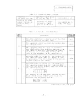
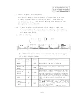
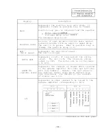

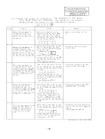


Display
Description
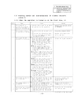
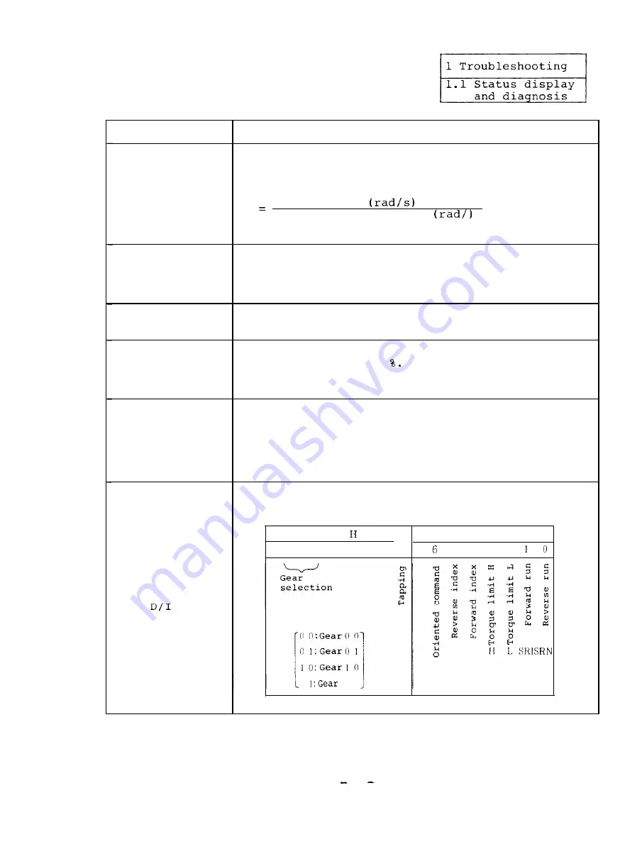
Represents the position loop gain state. It
represents 0 when no position loop is formed.
GAIN
Position loop gain is obtained from the equation
Motor speed
Followed delay error
The standard value is 10.
An error of real spindle rotation angle against
POSITION DROOP
referred spindle rotation angle is named droop.
The unit is in pulses.
When no position loop is
formed,
the position droop is 0.
RPM
Represents the real motor speed.
(Motor speed)
The unit is in rpm.
Represents a ratio of load against the rating
MOTOR RATE
output.
The unit is
The 30-minute rating
output is 100%.
The motor rate is in the range
0 to 120%.
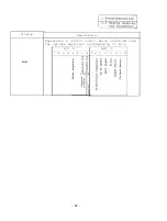
Represents the contents of alarms which occurred
in the spindle amplifier this time and last time
ALARM NO.
with code numbers.
However,
the last alarm is
(Spindle alarm) the smallest number alarm which differs from
this time alarm.
For details of the contents
of alarms, see 1.3.3.
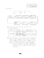
Represents an input command to be issued to the
spindle amplifier corresponding to bits.
D/I
D/I L
7
6 5 4 3 2
10
7 5 4 3 2
1
1 1
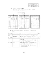
Continued on the next page.
11
Summary of Contents for FREQROL-SF
Page 100: ... 3 Display lamps See Appendix 8 2 4 Check terminals See Appendix g 3 95 ...
Page 101: ......
Page 102: ......
Page 103: ......
Page 104: ......
Page 105: ......
Page 106: ......
Page 107: ......
Page 108: ......
Page 109: ......
Page 110: ......
Page 111: ......
Page 128: ......
Page 129: ......
Page 130: ......
Page 131: ......
Page 132: ......
Page 133: ......
Page 134: ......
Page 135: ......
Page 136: ......
Page 137: ......
Page 138: ......
Page 139: ......
Page 140: ......
Page 141: ......
Page 142: ......
Page 143: ......
Page 144: ......
Page 145: ......
Page 146: ......
Page 147: ......
Page 148: ......
Page 149: ......


