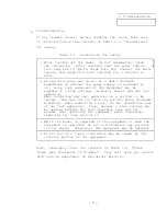


1 Troubleshooting
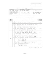
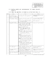
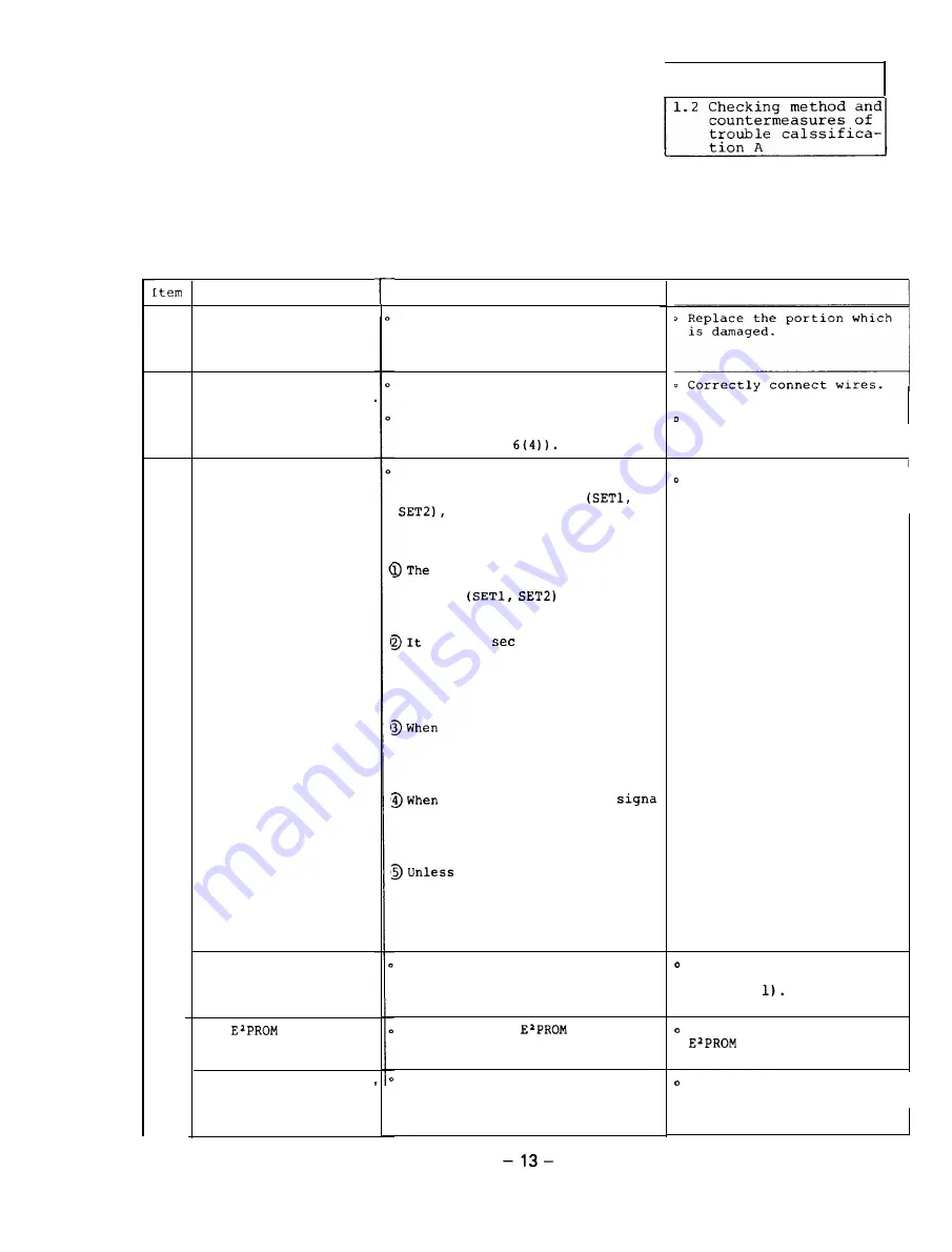
1.2 Checking method and countermeasures of trouble classifi-
cation A
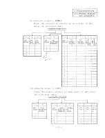
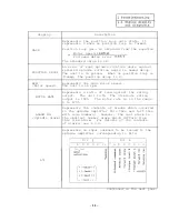
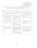
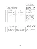
1.2.1 When the amplifier is turned on at the first time, it
1
2
3
-
-
4
5
6
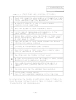
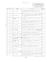
The amplifier is
knocked and damaged
when the equipment is
operated or installed.
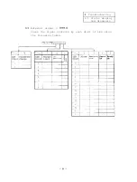
Cause
The external wiring
is incorrect or broken
The signal ON/OFF
sequence is incorrect.
The ground wiring is
not conducted.
The
number is
incorrect.
The switch and setting
pins are incorrectly
set.
Check
Visually check there is an abnor-
mal portion on the amplifier.
Visually check the external wir-
ing.
Check that the indication lamp
LED 1 on the SF-PW card lights
(see Appendix
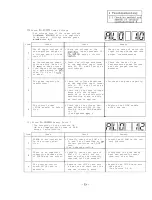
Check the sequence among the NC
ready ON signal, spindle ampli-
fier CON1 ready signal
forward rotation signal,
reverse rotation signal, and
orientation signal taking care
of the following items.
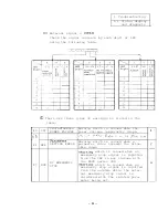
NC ready ON signal and
spindle amplifier CON1 ready
signal
become
ready when both the signals are
turned on.
takes 1
or more until tht
command of the forward rotation
signal,
reverse rotation signal
or orientation signal is
received after the ready ON
state.
both the forward rotation
signal and reverse rotation
signal are turned on at a time,
the motor does not rotate (it
becomes the DC exciting state).
the forward rotation
or reverse rotation signal is
inputted when the speed refere-
nce is 0,
the motor becomes the
DC exciting
State.
the forward rotation
signal,
reverse rotation signal
or orientation signal is input-
ted the motor is in the free
run state where the base
shut-off takes place.
Check the ground wirings of the
power,
amplifier,
and motor and
shield ground wiring of the
detector command.
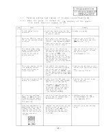
Check that the
number
conforms with the amplifier mode
name and motor type name.
Check the set positions of the
switches and setting pins by
comparing them with the attach-
ed setting pin list (Reference
1.11.
Remedy
Replace the broken wire
with a new one.
Change the signal sequence.'
Correctly connect the
ground wirings (see
Appendix
Replace the incorrect
with a correct one.
Correctly set the switches
and setting pins.
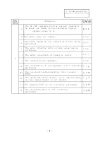
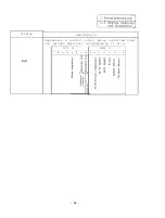
Continued on the next page.
Summary of Contents for FREQROL-SF
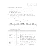
Page 100: ... 3 Display lamps See Appendix 8 2 4 Check terminals See Appendix g 3 95 ...
Page 101: ......
Page 102: ......
Page 103: ......
Page 104: ......
Page 105: ......
Page 106: ......
Page 107: ......
Page 108: ......
Page 109: ......
Page 110: ......
Page 111: ......
Page 128: ......
Page 129: ......
Page 130: ......
Page 131: ......
Page 132: ......
Page 133: ......
Page 134: ......
Page 135: ......
Page 136: ......
Page 137: ......
Page 138: ......
Page 139: ......
Page 140: ......
Page 141: ......
Page 142: ......
Page 143: ......
Page 144: ......
Page 145: ......
Page 146: ......
Page 147: ......
Page 148: ......
Page 149: ......


