


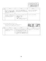

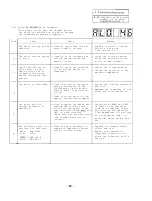
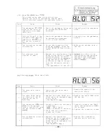
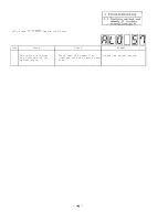


1 Troubleshooting
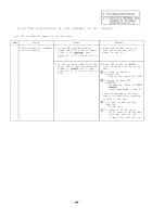
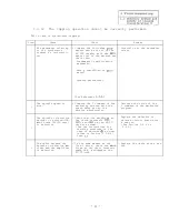
1.3.4
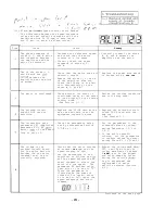
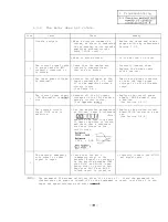
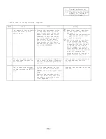
The motor does not rotate.
Item
Cause
Check
Remedy
Trouble analysis
When a rotation command is
Review the cause and take a
issued,
an alarm is indicated
proper action by referencing
on the display on the spindle
Section 1.3.3.
amplifier printed circuit
1
board (SF-CA card).
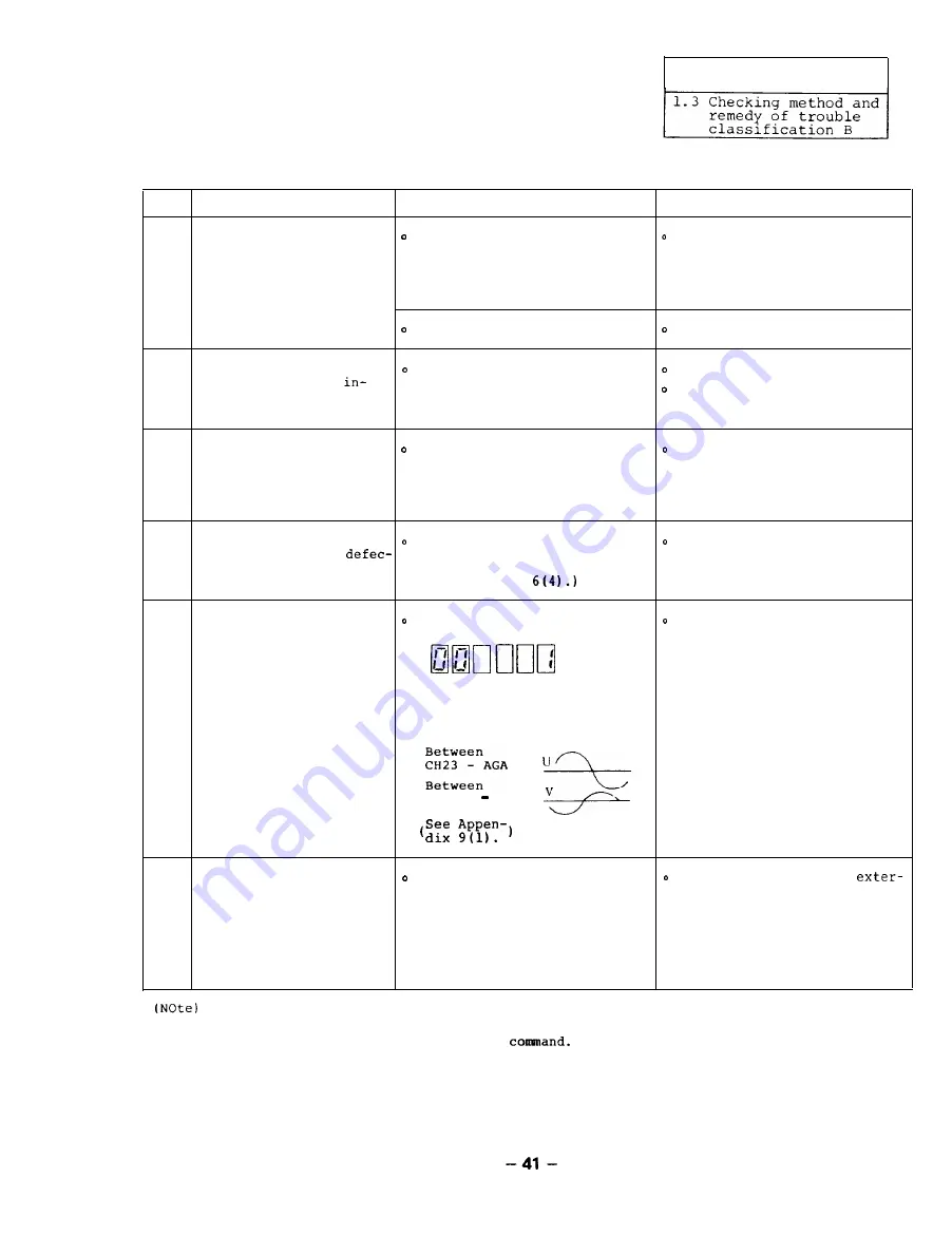
When no alarm occurs:
Go to the Item 2 or later.
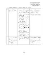
The control signal cable Check that the cables are
Correctly connect them.
or power cable is
correctly connected and
2
correctly connected or
they are not broken.
Replace the broken cable
is broken.
with a new one.
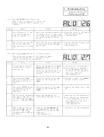
The input power voltage
Measure the voltages at the
Improve the power condition
is abnormal.
input terminals Xl, X2, and
so that the input power
3
X3 of the amplifier using a
voltage is in the allowable
circuit tester.
range.
(See Table 1.3.)
The control power supply
Measure all the DC output
Replace the control power
4
(SF-PW module) is
voltages of the SF-PW module
supply (SF-PW module) with
tive.
using a circuit tester.
a new one.
(See Appendix
(See Section 2.4.1.)
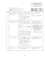
The printed circuit
Set the amplifier parameterer
Replace the printed circuit
board SF-CA card is
as follows,
input a reference
board SF-CA card with a new
defective.
(Note)
one.
(See Section 2.4.4.)
speed in the open loop state
to cause the motor to rotate,
and check that a reference
sine wave occurs on the
5
oscilloscope.
CH14 AGA
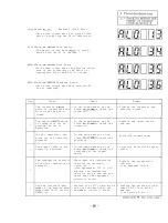
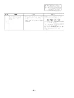
The external emergency
Check that the bit 2
Correctly connect the
stop signal or reset
(emergency stop) of the
nal signal cable.
signal is input.
external signal is turned on
6
or the portion between CON1
pins No.47 and No.48 (emer-
gency stop) or portion bet-
ween pins No.19 and No.20
(alarm reset) is turned on.
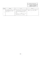
The parameter 00 becomes valid just after it is set to 1.
Since the parameter is
cleared when the power is turned off or the equipment is reset, just after 1 is set,
input the speed reference and start
Summary of Contents for FREQROL-SF
Page 100: ... 3 Display lamps See Appendix 8 2 4 Check terminals See Appendix g 3 95 ...
Page 101: ......
Page 102: ......
Page 103: ......
Page 104: ......
Page 105: ......
Page 106: ......
Page 107: ......
Page 108: ......
Page 109: ......
Page 110: ......
Page 111: ......
Page 128: ......
Page 129: ......
Page 130: ......
Page 131: ......
Page 132: ......
Page 133: ......
Page 134: ......
Page 135: ......
Page 136: ......
Page 137: ......
Page 138: ......
Page 139: ......
Page 140: ......
Page 141: ......
Page 142: ......
Page 143: ......
Page 144: ......
Page 145: ......
Page 146: ......
Page 147: ......
Page 148: ......
Page 149: ......


