HEAD OFFICE
: TOKYO BUILDING, 2-7-3 MARUNOUCHI, CHIYODA-KU, TOKYO 100-8310, JAPAN
HIMEJI WORKS : 840, CHIYODA CHO, HIMEJI, JAPAN
This manual confers no industrial property rights or any rights of any other kind, nor does it confer any
patent licenses. Mitsubishi Electric Corporation cannot be held responsible for any problems involving
industrial property rights which may occur as a result of using the contents noted in this manual.
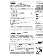
3) [BFM #5]: Data holding mode: While the programmable controller is in the STOP mode, the last output
value in the RUN mode will be held. To reset the value to the offset value, write the hexadecimal value
in BFM #5 as follows:
O = 0: Holds the output.
O = 1: Resets to the offset value.
Example: H0011 ...... CH1 and CH2 = Offset value CH3 and CH4 = Output holding
In addition to the above functions, the buffer memories can adjust the I/O characteristics of the FX
2N
-4DA,
and report the status of the FX
2N
-4DA to the PLC.
Buffer memories marked “W” can be written to using the TO instruction in the main unit.
The status of BFM #0, #5, and #21, (marked E) will be written to EEPROM, therefore the set values will be
retained even after turning off the power.
*1: Offset data:
Actual analog output value when corresponding output data (BFM #1 through #4) is 0
*2: Gain data:
Actual analog output value when corresponding output data (BFM #1 through #4) is +1,000
*3: When current output mode 1 (+4 mA to +20 mA) is set, the offset data will be automatically set to
+4,000 and the gain data to +20,000. When the current output mode 2 (0 mA to +20 mA) is set,
the offset data will be automatically set to 0 and the gain data to +20,000.
[BFM #8 and #9] Offset/gain setting command: Changes offset and gain values of channels CH1 through
CH4 by writing 1 to the corresponding Hex digits of BFM #8 or #9. The current values will be valid until this
command is output.
O = 0: No changes done.
O = 1: Change data value.
(Program example: see section 8.)
[BFM #10 through to #17] Offset/gain data: The offset and gain values are changed by writing new data to
BFM #10 through to #17. The units of the data to be written is mV or
µ
A. The data should be written and
then BFM #8 and #9 set. Note that the data value will be rounded down to the nearest 5mV or 20mA.
1) [BFM #20] Initialize: When K1 is written in BFM #20, all values will be initialized to the factory-default.
(Note that the BFM #20 data will override the BFM #21 data.) This initialize function is convenient if
you have an error in adjustment.
2) [BFM #21] I/O characteristics adjustment inhibit: Setting BFM #21 to 2 inhibits the user from
inadvertent adjustment of I/O characteristics. The adjustment inhibit function, once set, will be valid
until the Permit command (BFM #21=1) is set. The initial value is 1 (Permit). The set value will be
retained even after power-OFF.
3) [BFM #29] Error status: When an error occurs, use the FROM command to read out the details of the
error.
Bits b4 through to b9, b11, b13 through to b15 are not defined.
4) [BFM #30]The identification code for a special function block is read using the FROM instruction. The
identification code for the FX
2N
-4DA unit is K3020.The main unit can use this facility in the program to
identify the special block before commencing any data transfers from and to the special function block.
Bit
Name
Status when bit is set to "1"
(turned on)
Status when bit is set to "0"
(turned off)
b0
Error
Error if any of b1 through b4 is turned on
No error
b1
O/G error
Offset/gain data in EEPROM is abnormal
or a data setting error occurs.
Offset/Gain data normal
b2
Power supply error 24V DC power failure
Power supplied normally
b3
Hardware error
Defective D/A converter or other hardware Non-detective hardware
b10 Range error
The digital input or analog output value is
out of the specified range.
The input or output value is in the
specified range.
b12
G/O-Adjustment
prohibit status
BFM #21 is not set to "1".
Adjustable status
(BFM #21 = 1)
C H 4 C H 3 C H 2 C H 1
H
BFM
Description
W
#8
Offset/gain setting command CH1, CH2 Initial value H0000
#9
Offset/gain setting command CH3, CH4 Initial value H0000
#10
Offset data CH1
*1
Unit: mV or mA
Initial offset value: 0
Initial gain value: +5,000
*3
Output
mode 0
#11
Gain data
CH1
*2
#12
Offset data CH2
*1
#13
Gain data
CH2
*2
#14
Offset data CH3
*1
#15
Gain data
CH3
*2
#16
Offset data CH4
*1
#17
Gain data
CH4
*2
#18, #19
Reserved
W
#20
Initialize. initial value = 0
#21 E I/O characteristics adjustment inhibit (Initial value 1)
#22 - #28 Reserved
#29
Error status
#30
K3020 identification code
#31
Reserved
G 2
H
O 2
G 1
O 1
G 4
H
O 4
G 3
O 3
BFM #8
BFM #9
Note: BFM #’s marked E.
•
Values of BFM #0, #5, and #21, (marked E) are stored in the EEPROM memory of the FX
2N
-4DA.
BFM #10 to #17 are copied to EEPROM when the gain/offset setting command BFM #8, #9 is used.
Also, BFM #20 causes the resetting of the EEPROM memory. The EEPROM has a life of about
10,000 cycles (changes), so do not use programs which frequently change these BFMs.
•
A mode change of BFM #0 automatically involves a change of the corresponding offset and gain
values. Because of the time needed to write the new values to the internal EEPROM memory, a delay
of 3 s is required between instructions changing BFM #0 and instructions writing to the corresponding
BFM #10 through BFM #17.
Therefore, a delay timer should be used before writing to BFM #10 through #17.
7. OPERATION AND PROGRAM EXAMPLES
If the factory-default I/O characteristics are not changed and the status information is not used, you can
operate the FX
2N
-4DA using the following simple program. For the FROM and TO instructions, refer to the
FX Programming Manual (
ΙΙ
).
CH1 and CH2: Voltage output mode (-10 V to +10 V)
CH3: Current output mode (+4 mA to +20 mA)
CH4: Current output mode (0 mA to +20 mA)
Operation procedure
1) Turn OFF the power of the PLC, and then connect the FX
2N
-4DA. After that, wire the I/O lines of the
FX
2N
-4DA.
2) Set the PLC to STOP, and turn on the power. Write the above program then switch the PLC to RUN.
3) Analog values will be sent from D0 (BFM #1), D1 (BFM #2), D2 (BFM #3), and D3 (BFM #4) to the
respective output channels of the FX
2N
-4DA. When the PLC is in STOP, the analog values set before
stopping the PLC will remain output. (The output will be held.)
4) When the PLC is in STOP, the offset values can also be output. For a detailed description, refer to
Section 6, 3).
8. CAUTION REGARDING OPERATION
1) Check whether the output wiring and/or expansion cables are properly connected on the FX
2N
-4DA
analog special function block.
2) Check that the PLC system configuration rules have not been broken, i.e. the number of blocks, and
the total system I/O are within the specified range.
3) Ensure that the correct output mode has been selected for the application.
4) Check that there is no power overload on either the 5V or 24V power source, remember the loading
on the main unit or a powered extension unit varies according to the number of extension blocks or
special function blocks connected.
5) Put the main processing unit into RUN.
6) After turning ON or OFF the 24V DC power for analog signals, the analog output may fluctuate for
approximately 1 second. This is due to time delays in the power supply from the main unit or
differences in start time. For this reason, be sure to take preventive measures so that this output
fluctuation will not affect the external units.
[Example of preventive measure]
9. ADJUSTMENT OF the I/O CHARACTERISTICS
9.1 I/O characteristics
The standard characteristics (factory default) are shown by the solid lines in the figure below. These
characteristics can be adjusted according to the conditions of the user’s system.
M8002
initial pulse
TO K1 K0 H2100 K1
Write the data for CH1 to D0, CH2 to D1,
CH3 to D2 and CH4 to D3.
TO K1 K1 D0 K4
M8000
RUN
monitor
Write data in respective data registers while observing the
following ranges:
Data register D0 and D1: -2,000 to +2,000 Data registers D2 and
D3: 0 to +1,000
(H2100)
→
BFM #0
CH1 and CH2: Voltage output CH3: Current output (+4mA to
+20 mA) CH4: Current output (0 mA to +20 mA)
Data register D0
→
BFM #1 (output to CH1)
Data register D1
→
BFM #2 (output to CH2)
Data register D2
→
BFM #3 (output to CH3)
Data register D3
→
BFM #4 (output to CH4)
2 4 V D C p o w e r
s u p p l y
F X - 4 D A s p e c i a l
f u n c t i o n b l o c k
2 N
A n a l o g d a t a c u t
O F F c i r c u i t
E x t e r n a l
a n a l o g u n i t
P o w e r s w i t c h
A n a l o g
o u t p u t
D i g i t a l i n p u t
+ 1 0 V
+ 1 0 . 2 3 5 V
- 2 , 0 0 0
+ 2 , 0 0 0
- 1 0 V
- 1 0 . 2 4 V
-2
,0
48
+2
,0
47
+ 5 V
o u
t p u
t m
o d
e 0
+ 1 , 0 0 0
A n a l o g
o u t p u t
+ 4 m A
D i g i t a l i n p u t
+ 2 0 m A
0
+ 1 , 0 0 0
O u t
p u t
m o d
e 1
A n a l o g
o u t p u t
+ 2 0 m A
0
D i g i t a l i n p u t
+ 1 , 0 0 0
O u
t p u
t m
o d e
2
Standard characteristics
of voltage output
Standard characteristics of
current output (+4mA to +20mA)
Standard characteristics of
current output (0mA to +20mA)
... Gain value
: Analog output value when the digital input is +1,000
... Offset value : Analog output value when the digital input is 0
Offset and gain can be set independently or together. Reasonable offset ranges are -5V to +5V or -20mA
to +20mA, and gainvalue-offset value=1V to 15V or 4mA to 32mA.
Gain and offset can be adjusted from software in the main unit.
When the slope of the I/O characteristic line is steep:
Slight changes to the digital input will greatly increase or reduce the analog output.
When the slope of the I/O characteristic line is gentle:
Slight changes to the digital input will not always change the analog output.
Note that the resolution (minimum possible change of analog output) of the FX
2N
-4DA is fixed.
9.2 Adjustment of I/O Characteristics
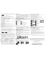
An example program for adjustment is shown below. The example shows that for channel CH2 of FX
2N
-
4DA block No.1, the offset value is changed to 7 mA, and the gain value to 20 mA. Note that for CH1,
CH3, and CH4, the standard voltage output characteristics are set.
10.TROUBLESHOOTING
If the FX
2N
-4DA does not operate properly, check the following items
1) Check the external wiring. Refer to section 4 of this manual.
2) Check status of the POWER indicator lamp (LED) of the FX
2N
-4DA.
On
: The extension cable is properly connected.
Off or flash : Check connection of extension cable. Also check the 5 V power supply capacity.
3) Check status of the 24 V power indicator lamp (LED) of the FX
2N
-4DA.
On : 24 VDC is supplied.
Off : Supply 24 VDC (+10%) to the FX
2N
-4DA.
4) Check the status of the D/A conversion indicator lamp (LED) of the FX
2N
-4DA.
Flash
: D/A conversion is normal.
On or off : The ambient conditions are not suitable for the FX
2N
-4DA, or the FX
2N
-4DA is defective.
5) Check that the external load resistance connected to each analog output terminal does not exceed
the capacity of the FX
2N
-4DA drive (voltage output: 2k
Ω
to 1 M
Ω
/ current output: 500
Ω
).
6) Check the output voltage or current value using a voltmeter or ammeter, and confirm that the output
meets the I/O characteristics. If the output does not meet the I/O characteristics, adjust the offset and
gain again. Refer to section 9.
z
▲
X010
SET M0
TO K1 K0 H0010 K1
P
TO K1 K21 K1 K1
P
M0
T0
TO K1 K12 K7000 K1
P
TO K1 K13 K20000 K1
P
TO K1 K8 H1100 K1
T0
T1
TO K0 K21 K2 K1
P
T1
RST M0
P
K30
K30
OPERATION START
(K7000)
→
BFM#12
Sets the offset data. (Offset value: 7 mA)
OPERATION END
(H0010)
→
BFM#0 Sets the
mode of the output channel.
(K1)
→
BFM#21
Permits adjustment of I/O
characteristics.
(K20000)
→
BFM#13
Sets the gain data. (Gain value: 20 mA)
(H1100)
→
BFM#8
CH2 offset/gain setting command
(K2)RBFM#21
Inhibits adjustment of I/O characteristics
D i g i t a l i n p u t
+ 1 , 0 0 0
A n a l o g
o u t p u t
+ 7 m A
+ 2 0 m A
0
Note
To test the withstand voltage of the FX
2N
-4DA, connect all the terminals to the grounding terminal.
Manual number : JY992D65901
Manual revision : C
Date
: March 2007


