FX2NC Series Programmable Controllers
Installation notes 3.
3-18
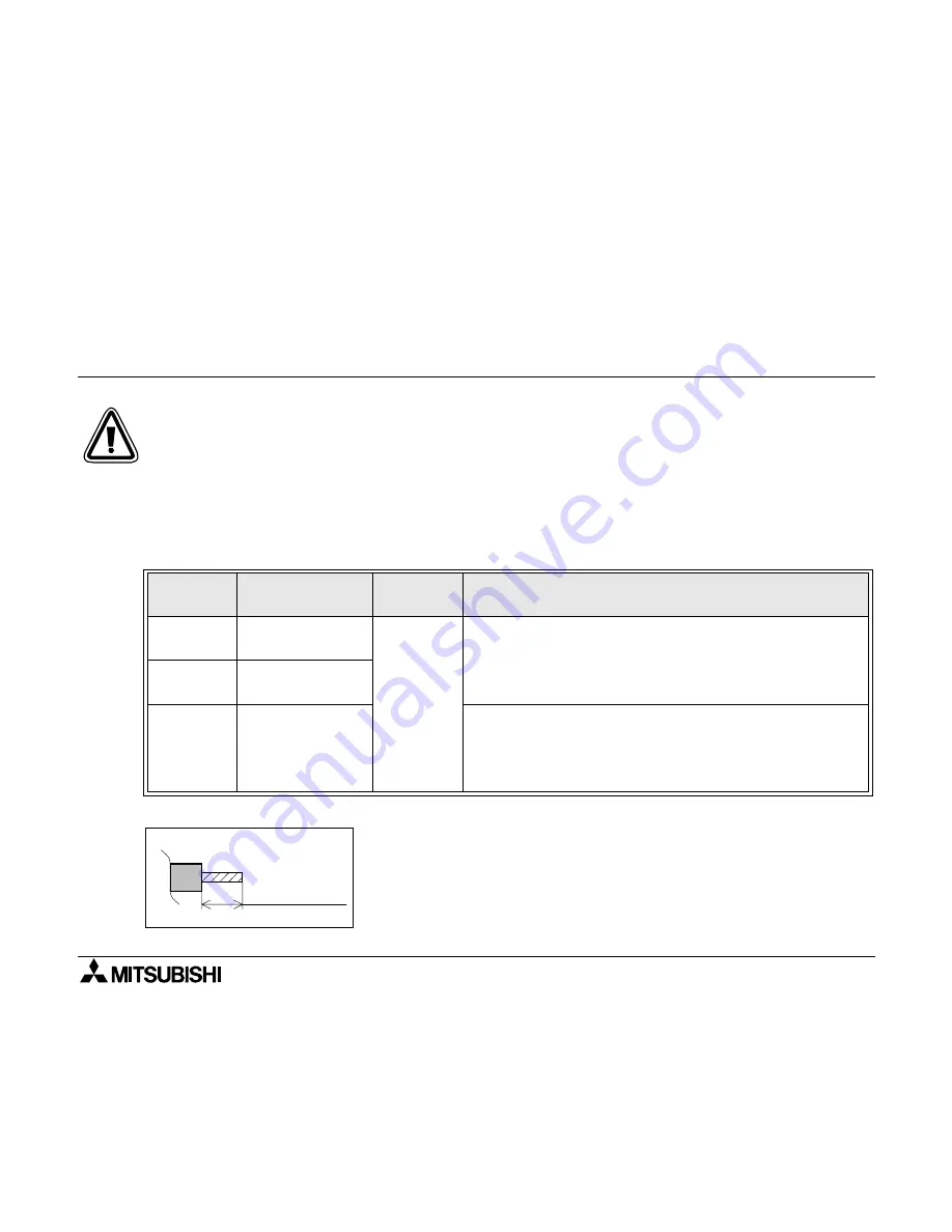
Figure 3.14:Cable end treatment size
Table 3.5 :Applicable cables
Model
Cable size
(stranded/single)
Tightening
torque
Terminal
One cable
0.3 to 0.5 mm
2
(AWG 22 to 20)
0.22
to
0.25 N
⋅
m
• Stranded cable: Rip off sheath, twist core wires, then
connect cable as it is.
• Single cable: Rip off sheath, then connect cable as it is.
Two cables
0.3 mm
2
(AWG 22)
×
2 cables
Ferrules,
with plastic
i n s u l a t i n g
sleeve
0.3 to 0.5 mm
2
(AWG 22 to 20)
(Refer to outline
drawing of ferrule
shown later.)
• Ferrule with insulating sleeve (recommended)
AI 0, 5-8WH (manufactured by PHOENIX CONTACT)
• Caulking tool
CRIMPFOX UD6(manufactured by PHOENIX CONTACT)
The output connectors of FX
2NC
-16MR-T-DS are 4-point common type.
The output connectors of FX
2NC
-16EYR-T-DS are 8-point common type.
The output terminal block in the FX
2NC
-16EYR-T-DS has two COM1 or COM2 pins that are
connected to each other inside the main unit.
To connect the line to an external unit, shortcircuit these two pins at the external circuit so
that the load applied on each pin can be reduced.
Stranded cable/single cable
Approx. 9 mm
(0.35in)
Treat the end of a cable in accordance with the hardware warning
shown in the previous page.
Summary of Contents for FX2NC DS Series
Page 18: ...FX2NC Series Programmable Controllers Contents xvi ...
Page 20: ...FX2NC Series Programmable Controllers Introduction 1 ...
Page 50: ...FX2NC Series Programmable Controllers Terminal layouts 2 ...
Page 56: ...FX2NC Series Programmable Controllers Installation notes 3 ...
Page 78: ...FX2NC Series Programmable Controllers Installation notes 3 3 22 MEMO ...
Page 80: ...FX2NC Series Programmable Controllers Power supply 4 ...
Page 88: ...FX2NC Series Programmable Controllers Inputs 5 ...
Page 98: ...FX2NC Series Programmable Controllers Outputs 6 ...
Page 110: ...FX2NC Series Programmable Controllers Outputs 6 6 12 MEMO ...
Page 112: ...FX2NC Series Programmable Controllers Diagnostics 7 ...


