8.1 Communication Unit
8 - 1
1
OV
E
R
VI
EW
2
SYSTE
M
CO
N
F
IG
UR
A
T
IO
N
3
S
P
E
CI
F
ICA
T
ION
S
4
P
A
R
T
NA
ME
AND
SETTING
S
5
EMC AND
LO
W
VO
LT
AG
E
DIRE
C
T
IVE
6
IN
ST
AL
L
A
TI
ON
7
WIRING
8
OP
TI
ON
8.
OPTION
When GT16 is used with a communication unit or option unit, monitoring is not possible because the GOT cannot
recognize the unit using the standard monitor OS and communication driver of the version before GT Designer3 Version
1.00A or GT Designer2 Version 2.87R.
8.1 Communication Unit
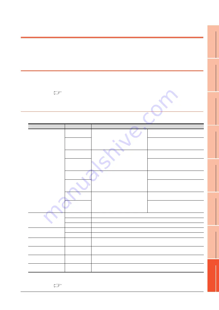
The communication unit is used to relate the GOT extension interfaces to the system at the connection destination.
To connect the communication unit, make Communication Settings for communications with a PLC.
For details of connection, refer to the following manual.
•GOT1000 Series Connection Manual for GT Works3 and a controller used
•GOT1000 Series Connection Manual for GT Designer2/GT Works2
8.1.1
Applicable communication unit
The following communication units are applicable for GT16
.
For how to install a communication unit, refer to the use's manual for the communication unit used.
The communication unit can be installed on another extension unit.
8.1.2 Installing multiple extension units in layers
Product name
Model
Description
Bus connection unit
GT15-QBUS
For QCPU (Q mode)/motion controller CPU (Q
series) connection (standard model)
For last GOT,
Number of IN side connectors: 1
GT15-QBUS2
For intermediary and last GOT,
Number of IN and OUT side connectors: 1 for
each side
GT15-ABUS
For A/QnACPU/motion controller CPU (A series)
connection (standard model)
For last GOT,
Number of IN side connectors: 1
GT15-ABUS2
For intermediary and last GOT,
Number of IN and OUT side connectors: 1 for
each side
GT15-75QBUSL
For QCPU (Q mode)/motion controller CPU (Q
series) connection (slim model)
For last GOT,
Number of IN side connectors: 1
GT15-75QBUS2L
For intermediary and last GOT,
Number of IN and OUT side connectors: 1 for
each side
GT15-75ABUSL
For A/QnACPU/motion controller CPU (A series)
connection (slim model)
For last GOT,
Number of IN side connectors: 1
GT15-75ABUS2L
For intermediary and last GOT,
Number of IN and OUT side connectors: 1 for
each side
Serial communication unit
GT15-RS2-9P
For RS-232 interface connection, connector type
GT15-RS4-9S
For RS-422 interface connection, connector type
GT15-RS4-TE
For RS-422 interface connection, terminal block type
MELSECNET/H
communication unit
GT15-J71LP23-25
Optical double loop unit
GT15-J71BR13
Coaxial bus unit
CC-Link IE Controller Network
communication unit
GT15-J71GP23-SX
Optical loop unit
CC-Link IE Field Network
communication unit
GT15-J71GF13-T2
Intelligent device station unit
CC-Link communication unit
GT15-J61BT13
Intelligent device station unit
CC-LINK Ver. 2 compliant
Serial multi-drop connection
unit
GT01-RS4-M
GOT multidrop connection unit
Summary of Contents for GOT 1000 GT16
Page 1: ...GT16 User s Manual Hardware ...
Page 2: ......
Page 14: ...A 12 INDEX REVISIONS WARRANTY ...
Page 210: ...App 17 ...
Page 212: ...Index 2 Transportation Precautions App 15 U USB environmental protection cover 2 17 8 19 ...
Page 217: ......


