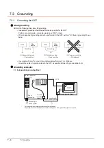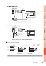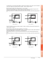
7.6 Grounding Extension Units
7 - 11
1
OV
E
R
VI
EW
2
SYSTE
M
CO
N
F
IG
UR
A
T
IO
N
3
S
P
E
CI
F
ICA
T
ION
S
4
P
A
R
T
NA
ME
AND
SETTING
S
5
EMC AND
LO
W
VO
LT
AG
E
DIRE
C
T
IVE
6
IN
ST
AL
L
A
TI
ON
7
WIRING
8
OP
TI
ON
(1) When using GT15-C
EXSS-1
(2) When using GT15-C
BS
For the both side GOTs, connect the LG and FG terminals of the terminal block on the GOT unit power and
ground them with a cable.
7.6.2
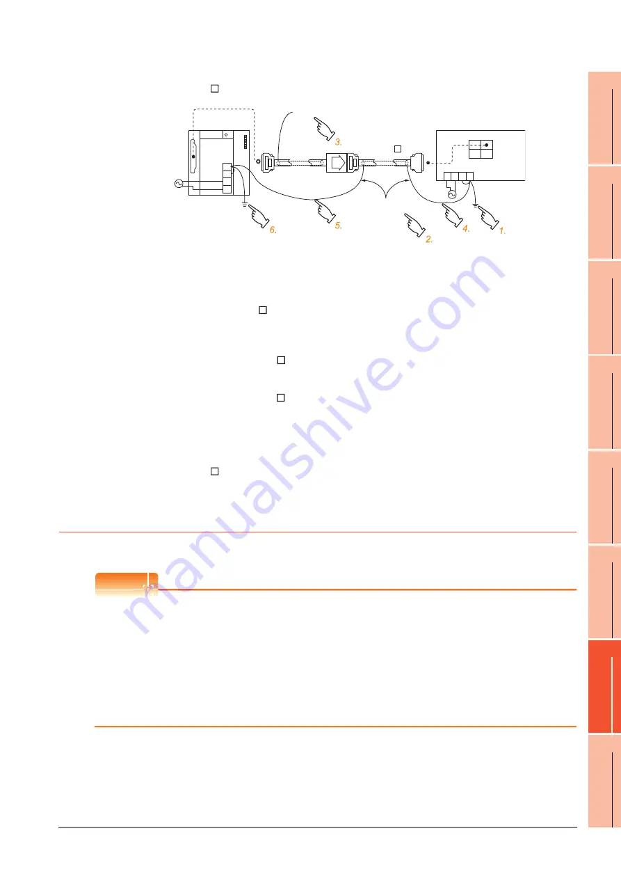
Wiring FG cable of CF card extension unit connection cable
The following explains wiring the FG cable when the CF card extension unit is installed on the GOT.
POINT
POINT
POINT
(1) Cables to be connected to CF card extension unit
Do not install the connection cable together with the main circuit lines (high voltage, large current) and I/O
signal lines.
(2) GOT terminal block
The terminal block layout of a GOT differs depending on the model.
Before wiring, check the terminal layout of the GOT to be used.
(3) Ground cables
Up to two ground cables can be connected to the LG and FG terminals of the GOT respectively.
For three or more ground cables, connect the third or later ground cables to the LG terminal.
1.
Connect the LG and FG terminals of the terminal block on the GOT unit power and
ground them with a cable.
2.
Use the GT15-C
BS's FG cable of 28cm or less.
3.
Do not connect the GT15-EXCNB's FG ground cable.
4.
Connect the GT15-C
BS's FG cable on the GOT side to FG of the GOT unit power's
terminal block.
5.
Connect the GT15-C
BS's FG cable on the PLC side to FG of the PLC's power supply
module.
6.
Connect the LG and FG terminals of the terminal block on the PLC and ground them
with a cable.
FG
LG
N
L
(GT15-EXCNB)
OUT
IN
FG
LG
N
L
(GT15-C BS)
Not connected
PLC
2SQ cables to
FG terminals,
28cm or less
GOT
Summary of Contents for GOT 1000 GT16
Page 1: ...GT16 User s Manual Hardware ...
Page 2: ......
Page 14: ...A 12 INDEX REVISIONS WARRANTY ...
Page 210: ...App 17 ...
Page 212: ...Index 2 Transportation Precautions App 15 U USB environmental protection cover 2 17 8 19 ...
Page 217: ......


