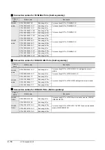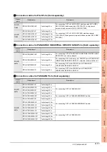
2.2 Component List
2 - 3
1
OV
E
R
VI
EW
2
SYSTE
M
CO
N
F
IG
UR
A
T
IO
N
3
S
P
E
CI
F
ICA
T
ION
S
4
P
A
R
T
NA
ME
AND
SETTING
S
5
EMC AND
LO
W
VO
LT
AG
E
DIRE
C
T
IVE
6
IN
ST
AL
L
A
TI
ON
7
WIRING
8
OP
TI
ON
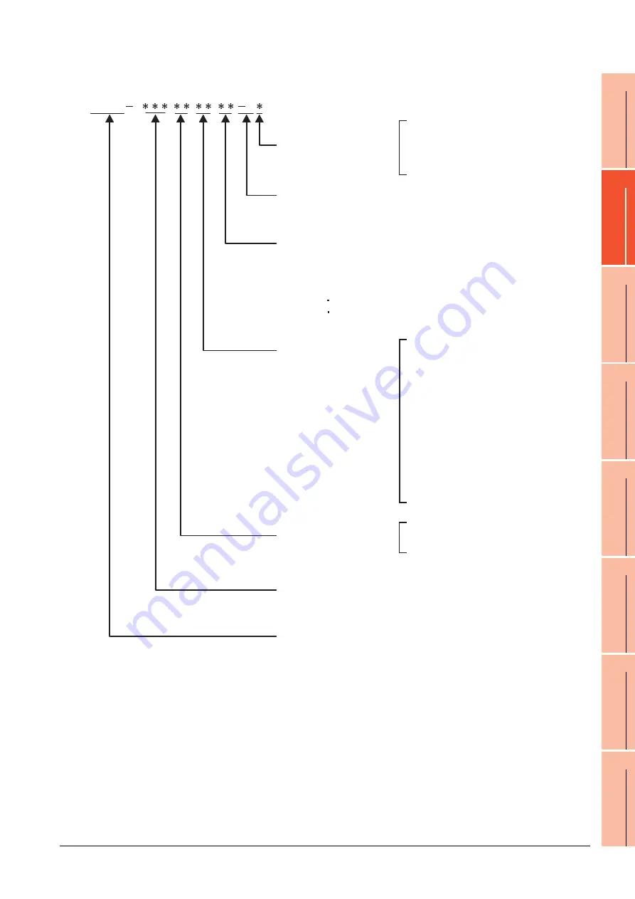
(3) Third party PLC connection cable
Connector pin type of the
connection target
(For third party PLC side)
Application classification
(For GOT1000 side)
Third party PLC connection cable
(Commonly used for GT16, GT15 and GT11)
G T 0 9 C
n
P: Plug (male)
S: Socket (female)
T: Solderless terminal
C: Preparatory soldering
Number of connector pins
(Indicates the number of terminals for solderless or
preparatory-soldered terminals.)
Example) Wirings are different for each PLC type.
Connecting targets are different, such as servo,
inverter, temperature controller.
Cable distinction numbers for one manufacturer's
products
(Two-digit sequence number: 01, 02, ...)
* When cable distinction is needed for one manufacture's
products
Cable classification
R2: For RS232 communication
R4: For RS422 communication
Length classification
* Indicated in 10cm unit.
Example) 3m : 30
30m: 300
01: For OMRON PLC
02: For YASKAWA PLC
03: For YOKOGAWA PLC
04: For HITACHI IEC PLC
05: For TOSHIBA PLC
06: For SHARP PLC
07: For ALLEN-BRADLEY PLC
08: For SIEMENS PLC
09: For PANASONIC INDUSTRIAL
DEVICES SUNXPLC
10: For FUJI PLC
11: For KEYENCE PLC
12: For JTEKT PLC
13: For HITACHI PLC
Summary of Contents for GOT 1000 GT16
Page 1: ...GT16 User s Manual Hardware ...
Page 2: ......
Page 14: ...A 12 INDEX REVISIONS WARRANTY ...
Page 210: ...App 17 ...
Page 212: ...Index 2 Transportation Precautions App 15 U USB environmental protection cover 2 17 8 19 ...
Page 217: ......


