6 - 4
6.2 Panel Cutting Dimensions
1
OV
E
R
VI
EW
2
SYSTE
M
CO
N
F
IG
UR
A
T
IO
N
3
S
P
E
CI
F
ICA
T
ION
S
4
PA
R
T
N
A
M
E
5
EMC DIRECTIVE
6
INS
TAL
L
A
TI
ON
7
WIRING
8
OP
TIO
N
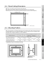
6.2 Panel Cutting Dimensions
Make holes in the panel according to the dimensions list below.
Also, ensure 10mm of space in upper and lower parts of the panel for mounting fixtures.
Horizontal format (If the vertical format is selected, the dimension must be rotated 90 degrees.)
6.3 Mounting Position
When mounting the GOT, the following clearances must be maintained from other structures and devices.
The below diagram represents a horizontal installation. (The same clearances must be maintained when
rotating the GOT 90 degrees clockwise for a vertical installation.)
Installation Environment
A,D
B
C
E
When the CF
card is not used
When the CF
card is used
In the presence of radiated-noise or
heat-generating equipment nearby
50 mm (1.97")
or more
80 mm (3.14")
or more
*1
50 mm (1.97")
or more
*2
100 mm (3.93")
or more
100 mm (3.93")
or more
In the absence of radiated-noise or
heat-generating equipment nearby
20 mm (0.79")
or more
20 mm (0.79")
or more
20 mm (0.79")
or more
20 mm (0.79")
or more
*1 Vertical Format....50 mm (1.97") or more (20 mm (0.79") or more)
*2 Horizontal Forma....80 mm (3.14") or more (20 mm (0.79") or more)
153
(6.03" )
+2
-0
+0.08"
-0
10 (0.4")
or more
10 (0.4")
or more
Unit: mm (inch)
121
+2
-0
(4.77" )
+0.08"
-0
B
A
C
D
E
Panel thickness: 2 to 4mm
(0.08 to 0.16inch)
Summary of Contents for GOT1000 GT11
Page 1: ......
Page 2: ......
Page 251: ...Index 2 U Utility function list 9 2 W Wiring 7 1...
Page 252: ...Index 3 MEMO...
Page 255: ......
Page 256: ......


