- 23 -
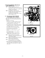
A/L LEVER
Boss
FLANGE of
LOADING ARM ASSY (SP)
Mark
Part with
Oblique Lines
A/L LEVER
Back
Apply GREASE (MOLYKOTE G PASTE) to the parts .
Fig. 2-31-2
Fig. 2-31-3
(Installation)
Note :
Install the LOADING ARM ASSY (TU) and
LOADING ARM ASSY (SP), according to the
following procedure, after installing the A/L
LEVER.
1. Apply GREASE (MOLYKOTE G PASTE)
[859D055O50] to the parts on the MAIN PLATE ASSY
specified in the Fig. 2-31-1.
2. Apply GREASE (MOLYKOTE G PASTE)
[859D055O50] to the parts on the A/L LEVER
specified in the Fig. 2-31-2.
3. Install the A/L LEVER so that the Mark on the A/L
LEVER faces to the FLANGE of the LOADING ARM
ASSY (SP), as shown in the Fig. 2-31-3.
Note :
The Part specified with Oblique Lines on the A/L
LEVER should be under the FLANGE of the
LOADING ARM ASSY (SP).
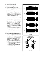
4. Install the LOADING ARM ASSY (TU) so that the
Marks on the LOADING ARM ASSY (TU) and on the
A/L LEVER will face each other, as shown in the Fig.
2-31-4.
5. Install the LOADING ARM ASSY (SP) so that the
mark on the LOADING ARM ASSY (SP) and the
Reinforcement Rib of the LOADING ARM ASSY (TU)
will face each other, as shown in the Fig. 2-31-4.
Note :
Be sure to replace the removed LOADING ARM
ASSY (SP) with a new one.
LOADING ARM
ASSY (TU)
LOADING ARM
ASSY (SP)
Reinforcement Rib
Mark
A/L LEVER
Mark
Fig. 2-31-4
Summary of Contents for HS-HD1100U
Page 57: ... 1 PARTS LIST 1 CABINET ASSEMBLY r 1 3 4 3 i o 0 2 6 t 7 2 1 ...
Page 61: ...DECK ASSEMBLY ...
Page 77: ......


