background image

3

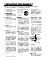
overhead power lines or other
electric light or power circuits, or
where it can fall into such power
lines or circuits.  When installing
an outside antenna system, ex-
treme care should be taken to
keep from touching such power
lines or circuits as contact with
them might be fatal.

17 Overloading

Do not overload wall outlets, ex-
tension cords, or integral conve-
nience receptacles as this can re-
sult in fire risk or electric shock.

18 Object and Liquid Entry

Never push objects of any kind
into this product through openings
as they may touch dangerous volt-
age points or short-out parts that
could result in a fire or electric
shock.   Never spill liquid of any
kind on the product.

19 Servicing

Do not attempt to service this
product yourself as opening or
removing covers may expose you
to dangerous voltage or other haz-
ards.  Refer all servicing to quali-
fied service personnel.

20 Damage Requiring Service

Unplug this product from the wall
outlet and refer servicing to quali-
fied service personnel under the
following conditions:
(a) When the power-supply cord

or plug is damaged.

(b) If liquid has been spilled, or ob-

jects have fallen into the product.

(c) If the product has been ex-

posed to rain or water.

(d) If the product does not oper-

ate normally by following the
operating instructions.   Ad-
just only those controls that
are covered by the operating
instructions as an improper
adjustment of other controls
may result in damage and will
often require extensive work
by a qualified technician to
restore the product to its nor-
mal operation.

(e) If the product has been

dropped or damaged in any
way.

(f) When the product exhibits a

distinct change in perfor-
mance – this indicates a need
for service.

21 Replacement Parts

When replacement parts are re-
quired, be sure the service techni-
cian has used replacement parts
specified by the manufacturer or
have the same characteristics as
the original part.  Unauthorized
substitutions may result in fire,
electric shock or other hazards.

22 Safety Check

Upon completion of any service
or repairs to this product, ask the
service technician to perform
safety checks to determine that
the product is in proper operat-
ing condition.

23 Heat

The product should be situated
away from heat sources such as
radiators, heat registers, stoves, or
other products (including amplifi-
ers) that produce heat.

CONDENSATION
Leave the VCR on, without a tape in it,
for 2 hours if the VCR has been ex-
posed to sudden changes in tempera-
ture.  Sudden temperature changes
cause moisture to form on the metal
parts inside the VCR.  This moisture can
cause the tape to stick and damage the
head.  Leaving the VCR on for a 2 hour
period will dry the inside of the VCR.

PROTECT THE POWER CORD
Do not damage the power cord.  Dam-
age to the power cord may cause a fire
or shock hazard.  When unplugging the
power cord, please hold it by the plug
and remove it carefully.

DO NOT PLACE HEAVY
OBJECTS ON  THE  RECORDER
Heavy objects placed on the recorder
will cause damage.

WHEN NOT IN USE
When you finish operating the re-
corder, always unload the cassette and
turn OFF the VCR POWER.

CARE OF THE VIDEO CASSETTE
TAPES
• Avoid violent vibration or shock.
• Do not place in a location where

strong magnetic fields exist (near a
motor, transformer or magnet).

• Never place or store in direct sun-

light.

• Avoid dusty places.
• Place the cassette in the cassette case

and store vertically.

• Never store tape in a high humidity

location.

INFORMATION
This equipment has been tested and found to comply with the limits for a Class B digital device, pursuant to Part

15 of the FCC Rules.  These limits are designed to provide reasonable protection against harmful interference
in a residential installation.  This equipment generates, uses, and can radiate radio frequency energy and, if not
installed and used in accordance with the instructions, may cause harmful interference to radio communica-
tions.  However, there is no guarantee that interference will not occur in a particular installation.  If this
equipment does cause harmful interference to radio or television reception, which can be determined by
turning the equipment off and on, try to correct the interference by one or more of these measures:

• Reorient or relocate the receiving antenna
• Increase the separation between the equipment and receiver
• Connect the equipment into an outlet on a different circuit than the receiver is connected
• Consult the dealer or an experienced radio/TV technician for help

Changes or modifications not expressly approved by the party responsible for compliance could void the user’s

authority to operate the equipment.  If necessary, consult the dealer or an experienced radio/TV technician
for additional suggestions.  You may find this booklet prepared by the Federal Communications Commission
helpful: How to Identify and Resolve Radio-TV Interference Problems.  This booklet is available from the US
Government Printing Office, Washington, D.C., 20402, Stock No.  004-000-00345-4.

Summary of Contents for HS-U576

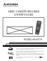
Page 1: ...stered trademarks of Gemstar Development Corporation The VCR Plus system is manufactured under license from Gemstar Development Corporation With VCR Plus C3 system this video cassette recorder can aut...

Page 2: ...duct IMPORTANT RECORDING OF COPYRIGHTEDTELEVISION PROGRAMS MAY VIOLATE COPYRIGHT LAW WARNING TO REDUCETHE RISK OF FIRE OR ELECTRIC SHOCK DO NOT EXPOSETHIS PRODUCTTO RAIN OR MOISTURE CAUTION TO PREVENT...

Page 3: ...ecording 22 Recording a Current Broadcast 22 OTR 23 OTR2 24 Audio andVideo Functions 25 Timer Recording 27 ConventionalVCR Timer Recording 27 Quick Program 29 VCR Plus System Programming 30 Timer Reco...

Page 4: ...1 Power Sources This product should be operated only from the type of power source indicated on the marking label If you are not sure of the type of power supply to your home consult your product deal...

Page 5: ...thout a tape in it for 2 hours if the VCR has been ex posed to sudden changes in tempera ture Sudden temperature changes cause moisture to form on the metal parts inside theVCR This moisture can cause...

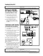
Page 6: ...st performance your dealer can help you customize these hookups and sell you any additional connection accessories that may be necessary to match your particular equipment and antennas 1 Make a list o...

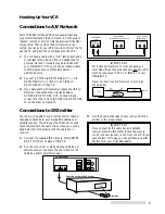
Page 7: ...TV Rear Panel OR Optional UHF VHF Splitter Optional 300 Ohm to 75 Ohm Matching Transformer Optional UHF VHF Combiner OR supplied coaxial cable OR From Antenna or Cable wall outlet VHF UHF VHF UHF IN...

Page 8: ...DEO VIDEO L MONO R AUDIO OUT AUDIO L R VIDEO OUT L R L R R White Red Yellow White Red Yellow TV Rear Panel VCR Rear Panel Because you purchased a Hi FiVCR you will want to take advantage of its superi...

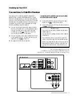
Page 9: ...Rear Panel Satellite Receiver Rear Panel Yellow If you have an RCA DSS Sony DSS Toshiba DSS Panasonic DSS Hughes DSS PRIMESTAR or DISH Network satellite system you can connect the satellite receiver...

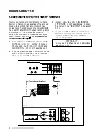
Page 10: ...el VCR Rear Panel Home Theater Receiver Rear Panel White Red White Red You may wish to connect your VCR to a Home Theater Receiver so that you can take advantage of the Surround Sound audio recordings...

Page 11: ...d on headphones for personal stereos This cable may be included with your Mitsubishi TV If not you can purchase a cable with mini jacks at your Mitsubishi dealer or electronics store 2 Connect ACTIVE...

Page 12: ...s picture to channel 3 or 4 This is called the video channel The factory has already selected channel 3 however if it is a broad cast channel in your area then you will need to change this to channel...

Page 13: ...the long narrow edge with the contents label faces you The other edge is hinged and should face theVCR The plastic window that shows the videotape should face up 2 Gently insert the tape evenly into...

Page 14: ...e ControllingVibration During Still Frame If the picture vibrates during still frame press the CHANNEL buttons on the front panel until the picture is steady Unloading aTape 1 Press EJECT on the front...

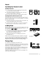
Page 15: ...l do this the first time you use the menus or set any audio and video functions 1 Make sure you are viewing the picture coming from yourVCR Press MENU on the remote control If this is the first time t...

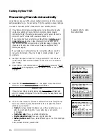
Page 16: ...not highlighted use the ADJUST buttons on the remote to highlight it 3 Press ENTER First Time Set Up menu will appear Press the ADJUST buttons to select Memorize channels Press ENTER IMPORTANT IMPORTA...

Page 17: ...mechanical dial or slide then your VCR will not be able to change channels on the cable box If your cable box will not respond to any of the codes your VCR cannot change channels on the cable box You...

Page 18: ...to perform this set up again unless your cable company changes their channel lineup or you move theVCR to a new address Satellite Receiver Control If you are using a satellite receiver you can set up...

Page 19: ...t available will flash on screen To correct this stop the tape or turn off the menus and switch theVCR to a local channel 6 You will see the screen for adding or deleting channels Use the ADJUST butto...

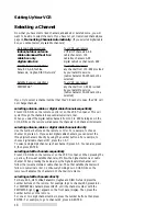
Page 20: ...NNEL on the remote will advance the channels in 10 channel increments selecting antenna cable or digital cable channels directly Use the number buttons on the remote control For example to choose chan...

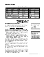
Page 21: ...to clock setting will be canceled See if the clock has been set on the front panel display on theVCR If theVCR displays the wrong time the time zone setting may not be correct To adjust this follow th...

Page 22: ...ontrol You will see theVCR Main Menu 2 Press the ADJUST buttons to select FirstTime Set Up Press ENTER FirstTime Set Up menu will appear Press the ADJUST buttons to select Set the clock Press ENTER 3...

Page 23: ...t the clock forward one hour If you select OFF theVCR will set the clock back one hour IMPORTANT IMPORTANT Any time you adjust this setting check your programmed recordings to be sure they are set to...

Page 24: ...cable box that theVCR cannot control select channel 3 or 4 on theVCR and change the channel on the cable box not on theVCR 5 Press REC on the remote or REC REC LENGTH on the front panel Recording wil...

Page 25: ...ame button adds 30 minutes to the OTR timer displayed on the front panel 6 Press REC REC LENGTH for each additional 30 minutes you want to add to the OTR timer up to 4 hours If you press the button 10...

Page 26: ...ach additional 30 minutes you want to add to the OTR2 timer up to 4 hours If you see End on the front panel display theVCR will record until the end of the tape If you have a cable box a digital cable...

Page 27: ...ou have yourVCR connected to a surround sound system set the audio monitor to Stereo Surround sound requires both left and right channels to create the rear channel effects While the VCR is not playin...

Page 28: ...feature Repeat playback Repeat play Use this function to repeatedly play a section of tape between two index marks See page 41 for more information on this feature PerfecTape PerfecTape function allo...

Page 29: ...een press ENTER 4 Program to record menu appears Press the ADJUST buttons to choose the channel you would like to record for example channel 2 Press ENTER If you are using a cable box that theVCR cann...

Page 30: ...me of the overlapped program will be highlighted in red color You will need to erase either of them 10 The programmed memory will appear on the Recap screen S next to the channel number indicates sate...

Page 31: ...hannel or input VCR Plus Program to record screen will appear IMPORTANT IMPORTANT If theVCR memory is full Program memory is full will appear for 3 seconds and then the Recap screen will appear Use CA...

Page 32: ...ber for the program you want to record is 5678 simply enter 5 6 7 8 See your local newspaper or TV Guide for PlusCode numbers 4 If you enter a number incorrectly press CANCEL When you have finished en...

Page 33: ...onal recording times select an empty program line by pressing the ADJUST buttons Press ENTER You will return to theVCR Plus Program to record screen Continue theVCR Plus programming procedure from ste...

Page 34: ...A tape without an erasure tab will be ejected To correct this load a tape with its erasure tab intact and turn off theVCR Do not overlap the recording times you enter into the VCR If you set two prog...

Page 35: ...t going into theVCR s menus Simply press POWER on the front panel once The programmed recording light will turn off and the program will be skipped If you decide not to skip the program press POWER on...

Page 36: ...R RESET on the rear panel to erase both the clock and all timer recordings To use TIMER RESET press it with a pencil or a ball point pen The power will turn off and the clock will be cleared All timer...

Page 37: ...Connect the audio cable to AUDIO OUT L and R on the playbackVCR and to AUDIO IN L MONO and R on the HS U576 If the playback VCR is mono use only the AUDIO IN L MONO on the HS U576 2 Connect a video ca...

Page 38: ...T on the HS U576 3 Set the audio monitor on the HS U576 to Stereo If the otherVCR is a monoVCR set the audio monitor on the HS U576 to Mono See Selecting and adjusting the audio and video functions on...

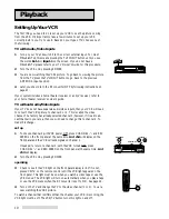
Page 39: ...slow motion mode theVCR will automati cally stop to avoid damage to the tape The picture may vibrate vertically when you pause theVCR s picture Still adjustment Sometimes during still frame the pictu...

Page 40: ...Automatic tracking will also resume when you eject the tape slow tracking Slow tracking is used to adjust the playback quality during slow motion playback and still frame You can only use slow trackin...

Page 41: ...ppear in the pictures 2 If you press FF or REW and hold it down for about 1 second the search speed will increase 3 To resume normal playback press FF or REW again quickly or press PLAY IMPORTANT IMPO...

Page 42: ...d index marks manually at any point during recording automatic index marks Whenever recording is begun from the STOP mode an index mark is automati cally added to the tape A message will indicate that...

Page 43: ...ar during fast forward and rewind from a stopped tape counter zero stop index searches rewinding for repeat playback Turn off the time gauge and the remaining time by pressing DISPLAY twice to make th...

Page 44: ...30 minutes If a control such as a menu function or channel selection is used or if there is a tape playing or being recorded theVCR will remain on 3 Complete steps 1 and 2 above Customize choices menu...

Page 45: ...ure prevention tab intact can be manually tested It will not automatically test recorded tapes you must choose to test those yourself 3 Complete steps 1 and 2 on the previous page Customize choices me...

Page 46: ...the PerfecTape function will not appear unless the tape is ejected Rental Xpress When you turn Rental Xpress ON theVCR will automatically rewind the tape eject the tape and then turn off after you pl...

Page 47: ...UICK PROGRAM VCR Plus to end programming Active A V Network turns off yourVCR unless a tape is currently playing or recording Active A V Network returns your TV to the channel it was on before or turn...

Page 48: ...or you get a new TV Once you have correctly set your remote control to operate your TV you will be able to use theTV POWER CHANNEL VOLUME and number buttons to operate yourTV IMPORTANT IMPORTANT Becau...

Page 49: ...When you wish to operate the otherVCR 1 On the remote with theTV VCR slide switch in the VCR position press VCR TV and the number 1 at the same time The remote will now send VCR A signals To reprogra...

Page 50: ...s are shown in the diagram to the right IMPORTANT IMPORTANT If the display shows E5 the video heads need to be cleaned Do not use a wet type cleaning cassette as it may damage yourVCR Use a dry type o...

Page 51: ...R TV SP EP ADJUST CANCEL ENTER ADJUST VCR TV STOP Stops a tape REW Rewinds a tape or reverse searches FF Fast forwards a tape or fast forward searches VCR TV slide switch Operates theVCR when set to t...

Page 52: ...IN cassette slot front panel display remote control sensor video input 2 jack audio input 2 jacks Location of Controls Front Panel POWER Turns theVCR on or off If you have programmed yourVCR to record...

Page 53: ...by theVCR AM PM SAP ST D OTR 2 SP EP LOCK VCR PT CH PROG REC REC PLAY M S H L R digital tracking time counter current time remaining time display channel display play light record light Front Panel Di...

Page 54: ...Stereo audio cables are also color coded red and white If you are receiving or sending a mono non stereo signal you should use only the left white terminal ANTENNA IN jack Attach an external antenna o...

Page 55: ...nel repeatedly for about 8 seconds until the current time display on the front panel shows 2 If a tape is not loaded press POWER to turn the power on If a tape is loaded wait about 3 minutes until the...

Page 56: ...of sight between the Emitter and the box s remote sensor Check that the IR Emitter is connected properly Sometimes a cable box needs to be set by the cable company to receive signals Contact your cabl...

Page 57: ...te control 1 IR emitter A A V Network active 45 connections to 9 jacks 9 52 adding channels 17 adjust button 49 adjusting tracking 38 advanced options 46 playback controls 37 antenna connecting 5 jack...

Page 58: ...n 49 quick program 29 quick search 39 R rear panel jacks 52 record button 49 50 record cancel 29 record light 51 record speed button 50 recording canceling programmed 34 canceling one in progress 29 c...

Page 59: ...cinta 6 bot n de parada STOP Oprima este bot n para detener la reproducci n de una cinta 7 bot n de grabaci n REC Utilice este bot n para comenzar la grabaci n 8 bot n de pausa PAUSE Utilice este bot...

Page 60: ...nar el idioma 6 Despu s de seleccionar el idioma que desea oprima el bot n ENTER Luego oprima el bot n MENU para salir de los men s C mo poner el reloj 1 Oprima el bot n MENU en el control remoto para...

Page 61: ...59 Note...

Page 62: ...60 Note...

Page 63: ...T COVER damage caused by modification alteration repair or service of this product by anyone other than an authorized MITSUBISHI service center physical abuse to or misuse of the VCR operation in a ma...

Page 64: ...NICS AMERICA INC 9351 Jeronimo Road Irvine CA 92618 1904 www mitsubishi tv com 1999 Mitsubishi Digital ElectronicsAmerica Inc Printed in Japan 872C242A3 For your nearest Mitsubishi Authorized Service...

Reviews: