background image

 46" LCD Display Monitor

USER’S MANUAL
BEDIENERHANDBUCH
MANUAL DEL USUARIO
MANUEL UTILISATEUR
MANUALE UTENTE
GEBRUIKERSHANDLEIDING

Summary of Contents for LDT46IV

Page 1: ...46 LCD Display Monitor USER S MANUAL BEDIENERHANDBUCH MANUAL DEL USUARIO MANUEL UTILISATEUR MANUALE UTENTE GEBRUIKERSHANDLEIDING...

Page 2: ...h 16 Connecting a DVD Player with component out English 17 Connecting to a Stereo Ampli er English 18 Basic Operation English 19 Power ON and OFF Modes English 19 Power Indicator English 20 Using Powe...

Page 3: ...d power cord or equivalent to ensure FCC compliance 2 Please use the supplied shielded video signal cable 15 pin mini D SUB to 15 pin mini D SUB 2 This equipment has been tested and found to comply wi...

Page 4: ...mercury Disposal of the lamp or the LCD Monitor with the lamp may be regulated due to environmental considerations For disposal or recycling information please contact your local authorities or the El...

Page 5: ...G WHEN SETTING UP AND USING THE LCD COLOR MONITOR DO NOT REMOVE MONITOR BACK COVER There are no user serviceable parts inside and opening or removing covers may expose you to dangerous shock hazards o...

Page 6: ...screw for stand x 4 The following components are prepared as option External Speakers Screw for Clamper M4 x 8 x 2 Thumbscrew for Stand x 4 Stand x 2 Video Signal Cable D SUB to D SUB Cable User s Man...

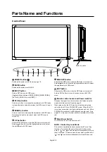
Page 7: ...to turn main power on off NOTE Control Key Lock Mode This control completely locks out access to all Control Key functions To activate the control key lock function press both of and and hold down sim...

Page 8: ...ayer HDTV device or Laser disc player AUDIO IN 1 2 3 To input audio signal from external equipment such as a com puter VCR or DVD player AUDIO OUT To output the audio signal from the AUDIO IN 1 2 and...

Page 9: ...O SETUP button To enter the auto setup menu See page 26 MUTE button To switch the mute function on off INPUT button Selects from input signal RGB1 RGB2 RGB3 RGB4 DVD HD VIDEO S and VIDEO AUDIO INPUT b...

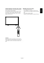
Page 10: ...e Control Point the top of the remote control toward the LCD monitor s remote sensor during button operation Use the remote control within a distance of about 7 m 23 ft from the front of the LCD monit...

Page 11: ...AA batteries To install or replace batteries 1 Press and slide to open the cover 2 Align the batteries according to the and indications inside the case 3 Replace the cover CAUTION Incorrect use of bat...

Page 12: ...ll stands 1 Please turn monitor off 2 After inserting stand in guide block fasten Thumbscrews on both sides of the monitor NOTE Install the stands so that their longer portions come to the front How t...

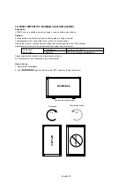
Page 13: ...portrait position will shorten the average life of the LCD backlight Operational Environment Temperature shall be limited as shown below Operational Temperature 5 35 C 41 95 F Environment Humidity 20...

Page 14: ...eep where the monitor may topple over or fall in case of an earthquake or other disaster 3 Ventilation Requirements for enclosure mounting To allow heat to disperse leave space between surrounding obj...

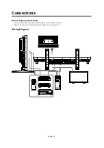
Page 15: ...h 14 Connections Before making connections First turn off the power of all the attached equipment and make connections Refer to the user manual included with each separate piece of equipment Wiring Di...

Page 16: ...the RGB 4 IN connector BNC on the LCD monitor use a signal cable which is available separately mini D sub 15 pin to BNC x 5 Select RGB 4 from the INPUT button When connecting one or more LCD monitors...

Page 17: ...nector can connect to HDMI output or DVI D output of PC To maintain display quality use a cable with a quality prescribed by DVI standards See 29 page DVI MODE The AUDIO IN 1 2 3 or HDMI can be used f...

Page 18: ...CD monitor use a separately available BNC connector cable You will need a BNC to RCA adapter to connect a DVD player with an RCA pin jack to the BNC connector cable not provided The AUDIO IN 2 and 3 b...

Page 19: ...or RCA on the LCD monitor and the audio input on the ampli er Do not reverse the audio left and right jacks The AUDIO IN 2 and 3 both RCA can be used for audio input For connection select AUIDO1 AUDIO...

Page 20: ...ing these two options 2 Pressing the power button NOTE Before pressing the power button be sure to turn on the Main Power button on the LCD monitor 3 Using the remote control NOTE Before operating the...

Page 21: ...ce Use the input button to set VIDEO Use the COLOR SYSTEM menu to set AUTO NTSC PAL SECAM PAL60 4 43NTSC according to your video format Picture Size RGB 1 2 3 4 DVD HD VIDEO FULL NORMAL DYNAMIC CUSTOM...

Page 22: ...Video Input mode Audio input mode Picture Size mode DVD HD AUDIO 3 SIZE FULL VIDEO S VIDEO Video Input mode Input Signal Colour System mode Audio input mode Picture Size mode VIDEO S NTSC AUDIO 3 SIZ...

Page 23: ...on Press UP or DOWN and PLUS or MINUS button to select function or control which you like Press INPUT button to decide Press INPUT button to decide Press EXIT button to exit Press UP or DOWN and PLUS...

Page 24: ...S VIDEO only Adjusts the noise reduction level Press button to increase reduction level Press button to decrease reduction level TINT INPUT RGB1 2 DVI HD DVD HD VIDEO S VIDEO only Adjust the tint of t...

Page 25: ...mage is the same as FULL size image when HDTV signal is input Selecting REAL image will be displayed 1 by 1 pixel CUSTOM ZOOM CUSTOM ZOOM will be selected when you select CUSTOM on the screen ZOOM mod...

Page 26: ...SET button to restore the factory preset Press EXIT button to cancel and then return to the previous menu AUDIO Main Menu PIP SIZE Selecting the size of picture inserted at the Picture in Picture PIP...

Page 27: ...es 4 directions UP DOWN RIGHT LEFT periodically Need setting the time for movement Movement area is approximately 10mm from original position Please locate the important information such as text withi...

Page 28: ...source change or warning message like as no signal or out of range A time between 1 to 10 seconds is available OFF TIMER To select OFF TIMER mode ON OFF In the OFF TIMER menu you can preset the monito...

Page 29: ...rlace signal to progressive Normally use this setting INTERLACE Disable the IP function NOTE This mode is better suited for motion pictures but it increases chance of image retention FILM MODE INPUT D...

Page 30: ...the current date and time for internal clock You should set this function when you use SCHEDULE SCHEDULE Programs the monitor s working schedule Schedule the power on and power off with hour and a da...

Page 31: ...remote control or use Power Management Function of monitor or use Schedule Function of monitor 3 Reducing the environmental temperature is effective for long life use When Protection board glass acryl...

Page 32: ...selection OSD appears at the upper left of the screen 4 Direct the remote controller at the remote control signal sensor of the PRIMARY monitor OSD appears on the monitor having the ID number you sele...

Page 33: ...S 232C 9600 bps 8 bits NONE 1 bits NONE This LCD monitor uses RXD TXD and GND lines for RS 232C control For RS 232C cable the reverse type cable should be used 2 Control command diagram The command is...

Page 34: ...Fh 72h 33h INPUT RGB 4 _r4 5Fh 72h 34h INPUT VIDEO _v1 5Fh 76h 31h INPUT DVD HD _v2 5Fh 76h 32h INPUT S VIDEO _v3 5Fh 76h 33h POWER OFF command should be operated over 1 minute after the power is turn...

Page 35: ...mputer automatically optimizing display performance Intelligent Power Manager System Provides innovative power saving methods that allow the monitor to shift to a lower power consumption level when on...

Page 36: ...al display devices MITSUBISHI ELECTRIC recommends displaying moving images and using a moving screen saver at regular intervals whenever the screen is idle or turning off the monitor when not in use I...

Page 37: ...or SCHEDULE OFF TIMER function is not working properly The SCHEDULE function will be disabled when the OFF TIMER is set If the OFF TIMER function is enable and the power to the LCD monitor is turned o...

Page 38: ...BNC INPUT RCA PIN JACK L R INPUT x 2 STEREO Mini Jack INPUT x 1 9 Pin Mini D sub Analog RGB Video 0 7 Vp p with 75 ohm terminated Separate HV sync TTL level Pos Neg 15 Pin Mini D sub BNC OUTPUT x 1 C...

Page 39: ...DIN 4P Name GND GND Y Luminance C Chroma Pin No 1 2 3 4 3 Digital RGB input HDMI R G B 1 R G B 2 1 2 3 4 5 6 7 8 9 10 11 12 13 14 15 16 17 18 19 Pin Assignment of HDMI connector TMDS Data2 TMDS Data2...

Page 40: ...39 0 39 60531 Fax 39 0 39 6053214 E mail info projector it mee com MEU NL MitsubishiElectric Europe B V Benelux Branch http www MitsubishiElectric nl Nijverheidsweg 23a 3641 RP Mijdrecht The Netherla...

Reviews: