


- 29 -
Variable operations are possible by adding external signals to the option connector.
A current of approximately 1.5 mA flows through the switches used for the input signal, so please use switch for minute current.
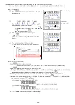
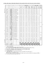
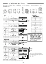
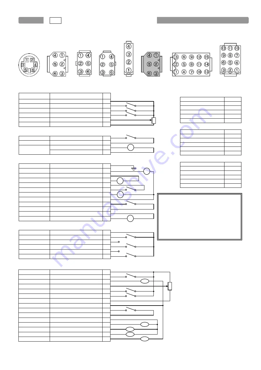
1. Connector Layout
Control panel Lever Encoder Detector Foot lifter Option A Option B Sewing machine
Lever
Signal name
Factory setting
0V
0V
1
IG
S1 : Run (Variable speed)
2
IH
S2 : Thread trimming
3
I I
S3 : Presser foot lifter
4
VC
VC : Variable speed command
5
+12V
+12V
6
Presser foot lifter
0V
0V
1
IF
F : presser foot input
2
OF
FU+ : presser foot lifter
3
FU- : presser foot lifter output -
4
Sewing machine
Ground
□
Ground
1
OB
□
W : Wiper output
2
+24V/(+30V)
□
+24V
3
OA
□
T : Thread trimming output
4
0V
□
0V
5
ID
□
TL : Thread trimmer cancel input 6
OD
□
L : Thread release output
7
+24V/(+30V)
□
+24V
8
IE
□
S7 : Backstitch input
9
0V/(+5V)
□
0V
10
+24V/(+30V)
□
+24V
11
OC
□
B : Backstitch output
12
Option A (Black)
0V
□
0V
1
IA
□
PSU : Up position stop input
2
+12V/(+5V)
□
+12V
3
IB
□
PSD : Down position stop input
4
O4
□
UPW : Needle Up position output 5
IC
□
S0 : Low speed input
6
Note 1 : Pin number 5 is for the signal output.
Option B
0V
□
0V
1
I4
□
No setting
2
O1
□
OT1 : Output
3
VC2
□
VC2 : Variable speed command
4
I5
□
No setting
5
I1
□
(*) IO1 : Input
6
+5V/(+12V)
□
+5V
7
+24V/(+30V)
□
+24V
8
I2
□
(*) U : Needle lift signal
9
0V
□
0V
10
+24V/(+30V)
□
+24V
11
O2
□
NCL : Needle cooler output
12
O7
□
No setting
13
O6/CP
□
No setting
14
O3
□
TF : "TF" output
15
Note 2 : Pin number 3,12,15 are for the solenoid output.
Note 3 : Pin number 13,14 are for the air valve output. (not for the solenoid output)
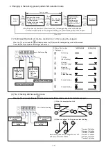
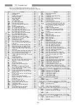
12 How to Use the Option Connector
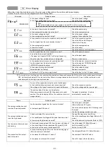
Communication /
Control panel (Note 4)
RXD1
1
RXD0
2
TXD1
3
0V
4
+12V
5
TXD0
6
Encoder (Note 4)
0V
1
EA
2
EB
3
+12V
4
Ground
5
-
6
Detector (Note 4)
0V
1
-
2
Ground
3
UP
4
DN
5
+12V
6
S1
S2
S3
External
variable
resister
10k
Ω
VC
F
FU
PSU
+12V max 40mA
PSD
UPW
S0
O1
O2
O3
O6
O7
VC2
I4
I5
I1
I2
External
variable
resister
10k
Ω
Sewing machine unit
TL
S7
B
W
T
L
Note4 : Please do not connect the connector of the
control panel /communication, the encoder,
and detector excluding our company's
products with the above connectors.
Moreover, please do not take out these
signals besides an original usage, and do
not connect them with other devices. It
causes the malfunction and the control box
breakdown, and our company doesn't
assume the responsibility.
Signals marked (*) will be changed as follows
when the function of name [4650], [4652], [4710]
or [4730] is selected in simple setting
I1: S7 Backstitch input
I2: IO1input


