background image

From the library of: Superior Sewing Machine & Supply LLC

Summary of Contents for LS2-190

Page 1: ...dustrial Sewing Machine Technlcai Information Model LS2 190 Automatic Undertrimmer Single Needle Lockstitch Sewing Machine ET 009A ITSUBISI ELECTRIC A MITSUBISHI From the library of Superior Sewing Machine Supply LLC ...

Page 2: ...3 Disassembling each unit 1 3 1 Knife drive mechanism i 3 2 Picker and thread trimming actuator 12 3 3 Knife assembly 12 4 Assembling and adjustment 12 4 1 Knife assembly 12 4 2 Picker and thread trimming actuator 15 4 3 Knife drive mechanism 18 4 4 Adjustment of length of needle thread end after trimming 23 4 5 Floating foot 23 4 6 Adjustment of touch back pushbutton position 24 4 7 Wiper 25 4 8 ...

Page 3: ... g Thread guide Pre tension Presser bar spring i Presser bar regula ting thumb screw Tension regulator Presser bar lifter 0 Presser bar Movable knife Q Eccentric shaft g Picker bracket Knife bracket 1 Feed bar Feed dog Fixed knife Thread guide From the library of Superior Sewing Machine Supply LLC ...

Page 4: ...al g Vertical shaft rod Reverse sewing lever Cam shaft bracket g Feed rock shaft Crank rod Feed lifting shaft Oil pump Hook shaft Thread trimmer solenoid Thread trimmer cam Gam follower crank Knee lifter Actuating crank Gam shaft 2 From the library of Superior Sewing Machine Supply LLC ...

Page 5: ...eedle hole Hook Full rotation automatic lubrication Thread trimmer type Standard type Full rotation automatic lubrication Thread trimmer type Heavy dury t e Bobbin case Bobbin case with racing prevetion spring Bobbin Thread trimmer type steel bobbin Thread trimmer Fixed and movable knives Thread trimmer smarting method Solenoid excitation Hiread trimmer drive system Gam drive Thread trimming speed...

Page 6: ...Note 1 T Touch lDack equipped TW Wiper and touch back equipped 4 From the library of Superior Sewing Machine Supply LLC ...

Page 7: ...From the library of Superior Sewing Machine Supply LLC ...

Page 8: ... link 6 Cam shaft Picker bracket Knife driving fork Movable knife crank Movable knife adjusting bracket Cam shaft bracket Trimmer cam Trimmer knife bracket Trimmer actuating crank Trimmer solenoid Roller shaft bracket Thread guide D Picker Fixed knife Picker drive crank Drive crank Cam follower crank From the library of Superior Sewing Machine Supply LLC ...

Page 9: ...enoid Wiper connecting g Pushbutton lever 0 Wiper connecting crank Wiper bracket Stepped shaft Wiper Back solenoid Side cover Gasket Plunger 1 Link Bushing Peed regulator Spring bracket Reverse sewing crank Reverse sewing lever shaft Reverse sewing lever g Spring Spring bracket Spring 7 m From the library of Superior Sewing Machine Supply LLC ...

Page 10: ...knife 2 Movable knife spreads and assorts the thread as it moves forwards Hook point Picker 3 Fixed knife Cutting blade area Thread guide groove Movable knife catches the two threads needle thread and bobbin thread as it retreats 8 Thread catcher hook 4 Thread trimming From the library of Superior Sewing Machine Supply LLC ...

Page 11: ...Passing the machine cords Table round Switch panel ake Switch panel ID iig fl j Power liriq Clutch Option Machine Speed Synchronizer Wiring between sewing machine and control box Note Before plugging or unplugging be sure to depress Power ON OFF I Ushbutton to OFF Pass two cables from the sewing machine through the round hole in the table and put the two plugs into the respecitive plug receptacles...

Page 12: ...ver 3 Operate the machine and stop it at a needleup position and make the following adjustments under this condition Adjustment 1 Loosen the set screw 5 while supporting the magnet disk hy hand fit the timing mark and by turning the balance wheel then tighten the set screw again 2 Step on the pedal and repeat kick back operations several times to ensure that the stop position is stabilized 3 Inser...

Page 13: ...nit construction Thanks to the unit construction each section can be independently adjusted and installed with ease 2 2 Cautions on adjustment A hook shaft cam drive system is employed in the trimmer In this drive system if the machine runs with the roller cam follower engaged in the trimmer cam groove at adjustment of the sewing machine for example the movable knife comes into contact with the ne...

Page 14: ...w the picker and thread trimming actuator can be removed 3 3 Knife assembly Fig l 3 3 1 Remove the hook 3 3 2 Remove the two knife assembly clamping screws Q Now the knife assembly can be removed Trimmer knife bracket D Solenoid bracket 3 Cam shaft bracket unit Picker Fig 1 4 Assembling and adjustment 4 1 Knife assembly 4 1 1 Fig 2 shows the standard installation and adjustment of the fixed knife ...

Page 15: ... 3 to the sewing machine To adjust the knife in reference to the needle position loosen the screws Center of needle position 2 m Knife bracket Fig 3 4 1 3 Setting of movable knife and engagement with fixed knife l In the standard engagement the fixed knife comes into contact with the movable knife when they are positioned as shown in Fig 4 13 Movable knife Fixed knife Fig 4 From the library of Sup...

Page 16: ...kwise Movable knife Movable Fig 5 Trimmer knife bracket iii Tighten the screw d iv Lightly pushing the movable knife crank against the trimmer knife bracket with the knives fully engaged tighten the set screw 0 4 1 4 Installing the knife assembly unit Install the knife assembly unit in reverse steps to the disassembling Replacing the movable knife To replace the movable knife proceed as follows 1 ...

Page 17: ...ker and thread trimming actuator 4 2 1 Installation 1 Assemble the parts as shown in Fig 6 2 Install the solenoid bracket using the two screws S 3 Install the picker bracket using the stepped screw B Picker Picker bracket Solenoid bracket Picker actuating link X nAg Rotary solenoid 0 Trimmer drive crank Picker drive crank Fig 6 4 2 2 Connecting the thread trimming actuator with cam shaft bracket u...

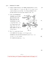
Page 18: ...a Trimmer drive crank Fig 7 4 2 3 Adjustment of plcKer Fig 8 1 Loosen the two screws so that a gap of 1 1 5mm is developed between the picker bracket and the feed bar and move the picker drive plate to properly position the picker 2 Position of picker in motion The picker should be so located that the picker end can enter the bobbin case recess center and is positioned in 0 5 1mm apart rom the bob...

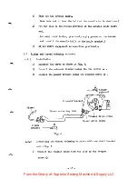
Page 19: ...titch at starting 0 5 1 an Bobbin Picker I l bBa W Picker drive plate D Fig 8 4 2 4 Adjustment of needle thread tension releasing 1 Securely clamp the flexible wire end sleeve witn the holder 2 2 Hold the wire g by the plate Lightly pull the wire to eliminate slack of the wire and tighten the screw Note Turn the balance wheel by hand to actuate the thread trimmer and make sure the tension discs op...

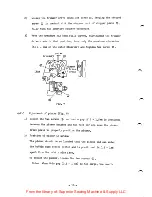
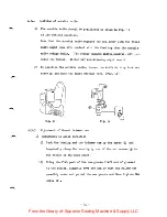
Page 20: ...of the unit 1 Adjusting the cam follower crank i Axial direction of the cam shaft iLoosen the screw to adjust the cam follower crank in the axial direction of the cam shaft ii Play in cercumferential direction of the cam shaft To eliminate play in the circumferential direction of the cam shaft adjust position of the roller 2 Adjusting the knife driving fork i Loosen the screw D to adjust position ...

Page 21: ...t bracket unit Pig 11 1 Put the movable knife crank pin into the knife driving fork B and install the cam shaft bracket unit by tightening three clamping screws 2 After the three screws have been tightened make sure the cam shaft can smoothly move 0 0 Fig 11 19 From the library of Superior Sewing Machine Supply LLC ...

Page 22: ...er shaft end and the cam circumference is within a range from 0 5mm to 1mm If the gap is out of the range loosen the roller shaft bracket set screw to adjust again 3 Make the stepped screw 3 come into contact with the stopper port of stopper plate manually and check the gap between the cam follower crank and the roller shaft bracket The standard gap ranges about 1 5mm 0 5 1 Roller shaft bracket r ...

Page 23: ...he movable knife loosen the knife driving fork set screw 3 and move the knife driving fork Fig 14 1 5 2 tm Fig 13 Fig 14 Adjustment of thread trimmer cam 1 Adjustment in axial direction i Lock the bushing and the trimmer cam by the screw 3 and temporally clamp the bushing by one of the set screws g to the recess of the hook shaft ii Bring the flat part of the cam gi oove left end of groove to the ...

Page 24: ...immer cam set screws 0 ii Match the second timing mark put on the balance wheel to the reference mark on the arm iii Bring the flat portion of the cam groove left end of groove to the roller and press the roller shaft to plung the roller into the cam groove iv Keeping this condition turn only the trimmer cam forward ly until the roller begins being pressed up by cam groove then secure the cam by t...

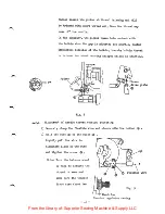
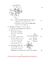
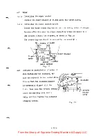
Page 25: ...gth of needle thread end after trimming 4 4 I This adjustement can be made by turning the pretension regulating nut g Turning the nut clockwise length of thread end becomes short Turning the nut counter clockwise length of thread end becomes long Fig 17 Floating foot Adjust the presser foot as follows 1 Adjust gap from the presser bar lower end surface to the presser bar bracket lower end surface ...

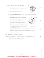
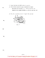
Page 26: ...with the presser lifter and then tighten the presser bar bracket set screw Loosen the screw 3 and return the stopper plate as it was Presser lifter lever Stopper plate D Throat plate Fig 18 2 5 b 2 Bis About 1 5mm 4 6 Adjustment of touch back pushbutton position Loosen the screw g and adjust the pushbutton positon 0 0 TTT Pushbutton 50 SQaa I Bed surface Fig 19 24 From the library of Superior Sewi...

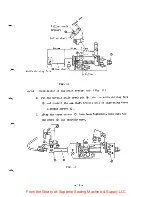
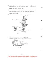
Page 27: ... should be secured by the seres Rotary solenoid A V Wiper connecting arm 1 5W 11H Wiper connecting crank 35 5 w Throat plate surface Pig 20 4 8 Cautions on installation of solenoid When installing the solenoid ad just the solenoid in horizontal direc tion so that the solenoid plunger is accurately aligned with the link Make sure the reverse sewing lever can smoothly move verti cally and then tight...

Page 28: ...aller than the tension in the ordinary single needle lockstitch machine considering the pressure of the spring for prevention of racing 4 Use a furnished bobbin Fig 23 When an aluminum bobbin is used wind thread on the bobbin with least tension as possible to revent deformation due to wound thread tension 4 10 Adjustment of feed dog inclination 4 10 1 Inclination of th feed dog should be adjusted ...

Page 29: ...haft d using a screwdriver to adjust Turning the pin clockwise feed dog sags that side Turning the pin coimter cloclcwise feed dog sags this side 3 After the adjustment be sure to tighten the screw g Fig 24 27 From the library of Superior Sewing Machine Supply LLC ...

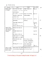
Page 30: ...4 1 2 Machine stops too early 4 2 Needle thread Tension disc does not 3 4 2 4 comes off needle open after thread trimming Trimming timing is too I3 A 3 5 early Gap between bobbin and 3 4 2 3 picker point is too large when picker is in motion Thread does not slip Polish thread guide smoothly retainer pretehsioner and tension regulator Thread guide is scored where thread slips Polish or replace El 4...

Page 31: ...ing bobbin thread guide groove El 4 9 Racing of bobbin causes Use bobbin case having El 4 9 entangling of thread racing prevention spring Bobbin thread tension is Adjust bobbin thread too tight tension to 10 15g 1 Too large chamfering on Use properly chamfered 1 1 presser foot and throat presser foot and plate throat plate Picker comes into con EI 4 2 3 tact with bobbin 29 From the library of Supe...

Page 32: ...A MITSUBISHI ELECTRIC CORPORATION HEAD OEElCf MtTSuetSMI OENKI BLOC MARUNOOCHI TOKYO 100 TELEX J24S32 CABLE MELCO TOKYO From the library of Superior Sewing Machine Supply LLC ...

Reviews: