


4. DAILY MAINTENANCE AND PERIODIC INSPECTION AND MAINTENANCE
4.3 Replacement Methods
– 45 –
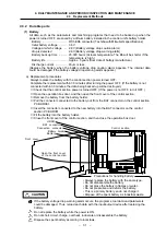
4.3.4 Control PCB
(1) Control section power supply PCB (HR081)
The control section power supply PCB is supplied with 24VDC from an external source. This PCB
generates the DC voltage required for each control PCB in the control section.
a) Replacement procedures
Always replace the control section power supply PCB with the control section power turned OFF.
A battery for backing up the memory is mounted on the control section power supply PCB, so as
with the battery, replace the control section power supply PCB within 30 minutes.
①
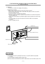
Check that the control section power is turned OFF. (If the power is not OFF, turn it OFF.)
②
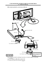
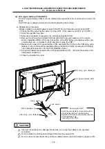
Open the operation box door, and then open the front cover of the control section.
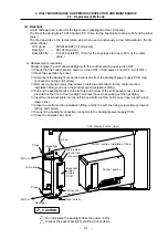
③
Disconnect all cables connected to the control section power supply PCB.
④
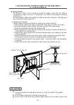
While holding the front upper and lower sections of the control section power supply PCB with
both hands, pull out the PCB from the control section.
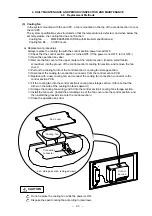
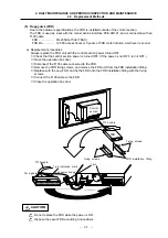
⑤
Remove the battery from the control section power supply PCB that was removed.
⑥
Replace with a new control power supply PCB, and install the battery.
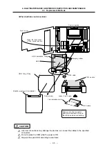
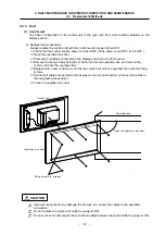
⑦
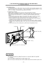
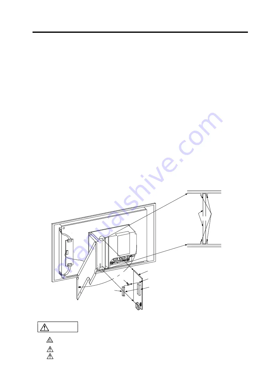
Install the control section power supply PCB into the control section. (Align the control section
power supply PCB with the PCB fixing guides on the inner side of the control section case,
and then install.)
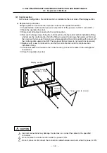
⑧
Connect all cables connected to the control section power supply PCB. (Connect the cables
to the designated connectors.)
⑨
Close the front cover of the control section, and then close the operation box door.
Control section case
Control section
power supply PCB
PCB fixing guides
Control section case
Control section
Open the front cover
of the control section.
Control section power supply PCB
BAT connector
Battery holder
Battery
Front cover
Connection
connector
Incorrect connections may damage the devices, so connect the cables to the specified
connectors.
Do not replace the control section power supply PCB while the power is ON.
Do not connect or disconnect the connection cables between each unit while the power is ON.
CAUTION


