10 - 8 10 - 8
10 MOUNTING AND INSTALLATION
MELSEC-ST
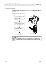
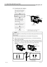
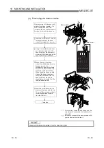
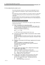
(5) Mounting the slice modules
Make sure that the head module,
base modules, end bracket and
end plate are fixed to the DIN
rail.
Push a slice module into the
base module (in the direction of
arrow) until it clicks and the
upper and lower module fixing
hooks are locked.
Make sure that all slice modules
are securely mounted.
Install the second and later slice
modules in the same manner.
Complete
Head module
DIN rail
Base module
Slice module
Wire the base module terminal
blocks (before mounting the slice
modules).
Module fixing hooks are located on the top
and bottom sides of a slice module.
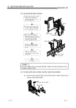
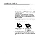
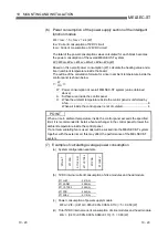
POINT
Mount a 1-slot width or 2-slot width type slice module while paying full attention to the
following points.
1-slot width type slice module is taken as an example in the figure below.
(1) Push in the slice module in the direction of arrow , so that the module fixing
hooks are securely locked.
(2) After installation, push the top and bottom sides of the slice module as shown in
figure and , in order to confirm that the hooks are correctly locked as shown
in figure . Incorrect locking may cause the slice module to drop off or
malfunction.
Slice module
Module fixing hook
Slice module
Slice module
Correctly locked
Module fixing hook
Incorrectly locked
Top side
Bottom side
Summary of Contents for MELESEC-ST
Page 1: ......
Page 2: ......
Page 23: ...A 21 A 21 MEMO...
Page 114: ...10 22 10 22 10 MOUNTING AND INSTALLATION MELSEC ST MEMO...
Page 125: ...11 11 11 11 11 EMC AND LOW VOLTAGE DIRECTIVE MELSEC ST MEMO...
Page 163: ...Index 2 Index 2 MEMO Ind...
Page 165: ......
Page 166: ......


