background image


A - 10                                                                                                                                                  A - 10 

11.1.4 External power supply module...................................................................................................... 11-  5 
11.1.5 Others ............................................................................................................................................ 11-  6 

11.2 Requirement for Compliance with the Low Voltage Directive ............................................................ 11-  7 

11.2.1 Standard applied for MELSEC-ST series..................................................................................... 11-  7 
11.2.2 MELSEC-ST series selection ....................................................................................................... 11-  7 
11.2.3 Power supply................................................................................................................................. 11-  8 
11.2.4 Control box .................................................................................................................................... 11-  8 
11.2.5 Grounding...................................................................................................................................... 11-  9 
11.2.6 External wiring............................................................................................................................... 11-  9 

12 TROUBLESHOOTING 

12-  1 to 12-16 

12.1 MELSEC-ST System Troubleshooting................................................................................................ 12-  1 

12.1.1 MELSEC-ST system checkup ...................................................................................................... 12-  2 
12.1.2 When RUN LED of slice module is off.......................................................................................... 12-  3 
12.1.3 When RUN LED of slice module (excluding intelligent function module) is flickering  

(1s interval).................................................................................................................................... 12-  4 

12.2 Power Distribution Module Troubleshooting ....................................................................................... 12-  6 

12.2.1 When RUN LED is flickering or off (Common to bus refreshing module and power  

feeding module)............................................................................................................................. 12-  6 

12.2.2 When ERR. LED is on or flickering............................................................................................... 12-  6 

12.3 I/O Module Troubleshooting ................................................................................................................ 12-  8 

12.3.1 When RUN LED is flickering or off ............................................................................................... 12-  8 
12.3.2 When ERR. LED is on or flickering............................................................................................... 12-  8 
12.3.3 Troubleshooting examples............................................................................................................ 12-12 

12.4 Error Code List ..................................................................................................................................... 12-15 

APPENDICES 

App-  1 to App-20


Appendix 1 Outer Dimension Drawings ....................................................................................................App-  1 

Appendix 1.1 Power distribution modules .............................................................................................App-  1 
Appendix 1.2 I/O modules......................................................................................................................App-  3 
Appendix 1.3 Base modules ..................................................................................................................App-  5 
Appendix 1.4 Accessory.........................................................................................................................App-  8 

Appendix 2 CC-Link ...................................................................................................................................App-  9 

Appendix 2.1 I/O data.............................................................................................................................App-  9 

Appendix 2.1.1 Power distribution modules ......................................................................................App-  9 
Appendix 2.1.2 Input modules ...........................................................................................................App-  9 
Appendix 2.1.3 Output modules ........................................................................................................App-10 

Appendix 2.2 I/O points sheet................................................................................................................App-11 

Appendix 3 PROFIBUS-DP .......................................................................................................................App-12 

Appendix 3.1 Input/Output Data.............................................................................................................App-12 

Appendix 3.1.1 Power distribution modules ......................................................................................App-12 
Appendix 3.1.2 Input modules ...........................................................................................................App-15 
Appendix 3.1.3 Output modules ........................................................................................................App-17 

Appendix 3.2 Maximum input/output points setting sheet ....................................................................App-19 

Appendix 4 Recommended Screwdriver...................................................................................................App-20 

INDEX 

Index-  1 to Index-  2


Summary of Contents for MELESEC-ST

Page 1: ......

Page 2: ......

Page 3: ...ons for usage Store this manual in a safe place so that you can take it out and read it whenever necessary Always forward it to the end user DESIGN PRECAUTIONS DANGER Create an interlock circuit on th...

Page 4: ...circuit or power wires Keep a distance of 100 mm 3 94 inch or more between them Not doing so could result in malfunctions due to noise INSTALLATION PRECAUTIONS CAUTION Use the MELSEC ST system in the...

Page 5: ...ct each cable connector Failure to do so may cause malfunctions due to poor contact DIN rail must be conductive make sure to ground it prior to use Failure to do so may cause electric shocks or malfun...

Page 6: ...ion due to a cable connection fault STARTUP AND MAINTENANCE PRECAUTIONS DANGER Do not touch the terminals while power is on Doing so could cause shock or erroneous operation Make sure to shut off all...

Page 7: ...ity from the human body Failure to do say cause a failure or malfunctions of the module When using any radio communication device such as a cellular phone keep a distance of at least 25cm 9 85 inch aw...

Page 8: ...to 5 Section 7 2 4 to 6 Jun 2006 SH NA 080456ENG E Partial addition Appendix 1 1 1 2 1 3 Aug 2006 SH NA 080456ENG F Partial addition Section 3 3 3 4 7 2 1 7 2 2 7 2 3 8 3 12 3 3 Apr 2008 SH NA 080456...

Page 9: ...3 1 7 3 2 7 3 3 Japanese Manual Version SH 080455 I This manual confers no industrial property rights or any rights of any other kind nor does it confer any patent licenses Mitsubishi Electric Corpora...

Page 10: ...EW 1 1 to 1 3 1 1 Features 1 2 2 HOW TO IDENTIFY MODULE NAMES 2 1 to 2 2 3 SYSTEM CONFIGURATION 3 1 to 3 15 3 1 System Configuration 3 1 3 1 1 CC Link 3 1 3 1 2 PROFIBUS DP 3 2 3 2 System Configuratio...

Page 11: ...3 3 Module with protection function 7 21 7 4 Part Names 7 22 8 ACCESSORIES 8 1 to 8 2 8 1 End Plate End brackets 8 1 8 2 Markers 8 1 8 3 Coding Elements 8 2 9 FUNCTIONS AVAILABLE BY USE OF SOFTWARE 9...

Page 12: ...RR LED is on or flickering 12 6 12 3 I O Module Troubleshooting 12 8 12 3 1 When RUN LED is flickering or off 12 8 12 3 2 When ERR LED is on or flickering 12 8 12 3 3 Troubleshooting examples 12 12 12...

Page 13: ...Link analog digital converter module Sold separately SH 080755ENG 13JZ12 MELSEC ST CC Link Digital Analog Converter Module User s Manual ST1DA2 V ST1DA2 V F01 ST1DA1 I ST1DA1 I F01 CC Link Describes t...

Page 14: ...le Sold separately SH 080444ENG 13JR70 MELSEC ST Thermocouple Input Module User s Manual ST1TD2 PROFIBUS DP Describes the specifications handling programming methods etc of the thermocouple input modu...

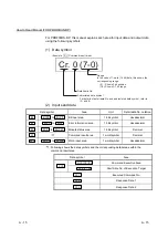
Page 15: ...Shows 0 bit position 7 0 Shows 0 7 bit range For details of detail data No and abbreviated data symbol refer to 2 and 3 2 Head module Master station a Remote input RX Data symbol Area name Unit Detail...

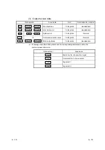
Page 16: ...to Bw n Bit output area 1 bit symbol Hexadecimal b Remote register RWr Data symbol Area name Unit Detail data No notation Ww Ww 0 to Ww n Word input area 1 word symbol Hexadecimal c Message transmiss...

Page 17: ...to 2 and 3 2 Input send data Data symbol Area Unit Detail data No notation Br Br 00 to Br FF Bit input area 1 bit symbol Hexadecimal Er Er 00 to ErFF Error information area 1 bit symbol Hexadecimal Mr...

Page 18: ...decimal Sw Sw 0 to Sw 7 System area 1 bit symbol Decimal Cw 1 Command execution area 1 bit symbol Decimal Ww Ww 00 to Ww 33 Word output area 1 bit symbol Hexadecimal 1 Following shows the data symbols...

Page 19: ...Module that transfers data between the head module and slice module and between the slice module and external devices including wiring Input module Modules that handle input data in units of bits Outp...

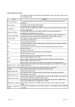
Page 20: ...are input from remote stations to the master station RY Remote output for CC Link Bit data that are output from the master station to remote stations RWr Remote register Read area for CC Link Data in...

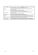
Page 21: ...maximum value is 63 This is used for specifying a command execution target Start slice No The start slice No assigned to the head module and slice modules Command Generic term for requests that are ex...

Page 22: ...equest Area Ew Error Clear Area Sw System Area Cw Command Execution Area Ww Word Output Area I O data Data input data output data transferred between the head module and the master station Br n bit in...

Page 23: ...A 21 A 21 MEMO...

Page 24: ...nes of the following MELSEC ST system devices power distribution modules I O modules base modules and accessories For details of the MELSEC ST system head module and intelligent function modules pleas...

Page 25: ...function module 24VDC 5VDC 5VDC Internal Bus Shield grounding Shield grounding Internal wiring External wiring 24VDC supply External power supply External SYS power supply 24VDC supply External power...

Page 26: ...y 1 Wiring the terminal block The screw clamp spring clamp type terminal block can be wired with a flat blade screwdriver and needs no special tools 2 Mounting and removing the modules The base module...

Page 27: ...maximum load current 0 5A For R Rated switching voltage rated switching current 200VAC 2A 24VDC 2A 1 For DE Rated input voltage 24VDC 3 For TE or TPE Rated load voltage 24VDC maximum load current 1 0...

Page 28: ...nal connection method Module type B Base module E Screw clamp terminal block S Spring clamp terminal block 3 3 line type 4 4 line type 6 6 line type X2 For 2 point input module X4 For 4 point input mo...

Page 29: ...ystem configuration when GX Configurator is used GX Configurator ST Remote station MELSEC ST Remote device station Remote station Remote station Remote station Master station MELSEC ST system 1 GX Dev...

Page 30: ...for the system configuration when GX Configurator is used GX Configurator ST Class 1 master station MELSEC ST Slave station No 60 MELSEC ST Slave station No 1 Slave station No 2 Slave station No 30 Sl...

Page 31: ...ding module are used Eternal power supply External SYS power supply Eternal power supply External AUX power supply Eternal power supply External AUX power supply System configuration details ST1H BT o...

Page 32: ...essary when the output module is mounted Base module for power feeding module Necessary when the power feeding module is mounted Base module for intelligent function module Used as base modules for th...

Page 33: ...tput module with fuse Source type ST1B 3Y2 ST1Y16 TE2 16 point 0 5A transistor output module with fuse Source type ST1B 3Y16 ST1Y2 TE8 2 point 2 0A transistor output module Source type ST1B 3Y2 ST1Y2...

Page 34: ...ST1A CKY 13 For Analog digital conversion module Voltage output ST1A CKY 14 For Analog digital conversion module Current output ST1A CKY 15 Platinum resistance temperature input module ST1A CKY 16 Fo...

Page 35: ...y are satisfied in advance 1 Whether intelligent function modules are used or not Not used Used 2 Whether contact output modules are used or not Not used Used Not used Used DC power supply 1 AC power...

Page 36: ...cluding contact output module Power distribution module Intelligent function modules DIN rail External SYS power supply External AUX power supply Fuse Fuse Noise filter A A can be replaced by B 24VDC...

Page 37: ...iguration where I O Modules 3 and Contact Output Modules Are Used Together Online module change to be executed Fig 3 5 Example of configuration where I O Modules 3 Contact Output Modules 1 and intelli...

Page 38: ...ignition To prevent this trouble provide fail safe circuits i e attach fuses outside the system External power supply must be turned ON OFF externally When turning ON OFF external power supply an inr...

Page 39: ...that for intelligent function module For details refer to Section 8 a 2 When performing online module change When configuring a system separate the power distribution module and external AUX power sup...

Page 40: ...an online module change refer to the Head Module User s Manual a Separate the power distribution module and external AUX power supply for each kind of the following slice modules When constructing th...

Page 41: ...ct the wiring of signal 24V at each point 2 When external device 2 wire type is connected to signals 24V Xn n 0 to F No need to connect Transistor output module ST1Y T Disconnect the signal Yn n 0 to...

Page 42: ...pply AUX input for each kind of the following slice modules For the I O modules or intelligent function modules separate the 24VDC power supply AUX input using another power distribution module ST1P D...

Page 43: ...the external power supply connected to the contacts of the contact output modules d When using the SSI absolute encoder input module ST1SS1 1 Mount the power distribution module on the immediate left...

Page 44: ...t max 4 Installation location Inside control panel Overvoltage category 1 II max Pollution level 2 2 max 1 This indicates the section of the power supply to which the equipment is assumed to be connec...

Page 45: ...r supply inputs and external AUX power supply inputs 10M or larger by 500VDC insulation resistance tester By noise simulator of 500Vp p noise voltage 1 s noise width and 25 to 60Hz noise frequency Noi...

Page 46: ...mp type ST1B S4P2 H SET ST1B E4P2 H ST1B E4P0 2 wire type shield Spring clamp type ST1B S4P2 H SET ST1B S4P2 H ST1B S4P0 2 wire type shield Applicable base module For adding bus refreshing module Scre...

Page 47: ...ng status LED indication at AUX 24VDC output AUX turns on Spring clamp type ST1B S4P2 D 2 wire type shield Applicable base module Screw clamp type ST1B S4P2 D 2 wire type shield Weight 0 03 kg Externa...

Page 48: ...the corresponding devices 1 Bus refreshing module and power feeding module The power distribution modules are classified into the bus refreshing module and power feeding module The bus refreshing mod...

Page 49: ...refreshing module or head module and the next bus refreshing module by the internal wiring of the base modules The total 5VDC internal current consumption of the slice modules mounted between the bus...

Page 50: ...values of 5VDC internal current consumption Slice position No Start slice No Number of occupied slices Module name Br n Bw n Wr n Ww n 5VDC internal current consumption Total value 24VDC current Tota...

Page 51: ...X4 DE1 ST1X4 DE1 ST1X4 DE1 ST1X4 DE1 ST1Y16 TE2 ST1Y16 TE2 ST1Y16 TE2 ST1Y16 TE2 ST1Y16 TE2 ST1Y2 R2 ST1DA2 V ST1DA2 V ST1DA2 V ST1DA2 V Total current consumption 1 725 A Total current consumption 0 3...

Page 52: ...since they can be ignored Consider inrush currents when inductive loads lamp loads or capacitive loads are connected to the contact output modules Item Description Load current of external device Indi...

Page 53: ...19 915A 3 12 6mm 604 8mm 13 54 1 ST1PSD 25 2mm 630 0mm 14 55 2 ST1DA2 V 4 4 2 0 095A 0 095A 0 065A 0 065A 4 12 6mm 642 6mm 15 57 2 ST1DA2 V 4 4 2 0 095A 0 190A 0 065A 0 130A 4 12 6mm 655 2mm 16 59 2...

Page 54: ...775 A ST1X4 DE1 ST1X4 DE1 ST1X4 DE1 ST1Y16 TE2 ST1PDD 2 ST1PDD ST1Y16 TE2 ST1Y16 TE2 ST1Y16 TE2 ST1Y16 TE2 ST1Y2 R2 ST1PSD ST1DA2 V ST1DA2 V ST1DA2 V ST1DA2 V External devices 16 sensors External dev...

Page 55: ...0 6mm 3 360A 6 720A 0 150A 1 395A 16 11 71 1 ST1PDD 12 6mm 201 6mm 0 060A 1 455A 12 72 8 ST1Y16 TE2 100 8mm 491 4mm 3 360A 3 360A 0 150A 1 605A 16 13 80 8 ST1Y16 TE2 100 8mm 592 2mm 3 360A 6 720A 0 15...

Page 56: ...to 3 The diagram of wiring to base module is printed on the surface When checking the wring diagram remove the symbol label 6 Slice module fixing hooks both ends Hooks for mounting removing the slice...

Page 57: ...slice module fault Internal bus error occurring RUN Off External power supply off hardware fault internal bus error occurring On Hardware fault On 0 5s intervals 24VDC voltage low ERR Off Normal On No...

Page 58: ...e Installation Direct installation to DIN rail Weight Refer to following table Terminal block type Model Weight ST1B S4X2 0 04kg ST1B S6X4 0 05kg ST1B S3Y2 0 03kg ST1B S4IR2 0 04kg ST1B S4X16 0 23kg S...

Page 59: ...s the base modules the 1 slot type power distribution module intelligent function module 2 4 point I O module and 8 slot width 16 point I O module are available Carefully select the base module that c...

Page 60: ...er into the top hole square and insert a wire into the bottom hole circular 2 Base module connector cover Connector for electrical connection between base modules The connector color changes depending...

Page 61: ...AC for 1 minute across DC external terminals and FG Insulation resistance 10M or larger by insulation resistance tester across DC external terminals and FG By noise simulator of 500Vp p noise voltage...

Page 62: ...n resistance 10M or larger by insulation resistance tester across DC external terminals and FG By noise simulator of 500Vp p noise voltage 1 s noise width and 25 to 60Hz noise frequency Noise durabili...

Page 63: ...urrent 2A total current of signal 24V During online module change maximum inrush current is 2A point 5ms Wiring method for common 16 points common Dielectric withstand voltage 500VAC for 1 minute acro...

Page 64: ...11 X0 91 X8 12 24G 92 24G 13 24V 93 24V 14 Shield 94 Shield 21 X1 101 X9 22 24G 102 24G 23 24V 103 24V 24 Shield 104 Shield 31 X2 111 XA 32 24G 112 24G 33 24V 113 24V 34 Shield 114 Shield 41 X3 121 X...

Page 65: ...er across DC external terminals and FG By noise simulator of 500Vp p noise voltage 1 s noise width and 25 to 60Hz noise frequency Noise durability First transient noise IEC61000 4 4 1kV bundle Protect...

Page 66: ...on Dielectric withstand voltage 500VAC for 1 minute across DC external terminals and FG Insulation resistance 10M or larger by insulation resistance tester across DC external terminals and FG By noise...

Page 67: ...tribution module Terminal Layout Terminal Block No Signal Name Terminal Block No Signal Name 11 Y0 91 Y8 12 24G 92 24G 13 Shield 93 Shield 21 Y1 101 Y9 22 24G 102 24G 23 Shield 103 Shield 31 Y2 111 YA...

Page 68: ...r larger by insulation resistance tester across DC external terminals and FG By noise simulator of 500Vp p noise voltage 1 s noise width and 25 to 60Hz noise frequency Noise durability First transient...

Page 69: ...al terminals and FG Insulation resistance 10M or larger by insulation resistance tester across DC external terminals and FG By noise simulator of 500Vp p noise voltage 1 s noise width and 25 to 60Hz n...

Page 70: ...ion Yes thermal protection short circuit protection Indicated by LED When protective function is activated ERR LED turns on and signal is output to head module Automatic recovery Wiring method for com...

Page 71: ...module Terminal Layout Terminal Block No Signal Name Terminal Block No Signal Name 11 Y0 91 Y8 12 24G 92 24G 13 Shield 93 Shield 21 Y1 101 Y9 22 24G 102 24G 23 Shield 103 Shield 31 Y2 111 YA 32 24G 11...

Page 72: ...e ratio within 5 External power supply for driving relay Current 35mA or less 24VDC when all points are ON Fuse No Dielectric withstand voltage 2830VAC rms 3 cycles altitude 2000m 6557 38ft Insulation...

Page 73: ...ve an inductive load make sure that the relay inside the module is ON OFF for 1 second or longer 2 When the counter time that uses DC DC converter as load is applied to an output module this causes th...

Page 74: ...T2 COM OUT1 Load OUT2 COM Load OUT1 OUT2 COM Sink type Sourse type 5 Caution points when using ST1Y2 TE8 Installing a fuse to each external terminal to prevent burn out of external devices and modules...

Page 75: ...e value based on actual use which is not guaranteed Therefore make sure to allow for a margin of error The specifications of the relay life is as follows Rated switching voltage current load 100 thous...

Page 76: ...a load so that the inrush current will be within the rated current of the module Connect the relay that can sustain inrush current outside the module 1 Inductive load Inrush current of inductive load...

Page 77: ...depending on a load Load of an incandescent bulb i io 3 to 10 times i io Approx 0 33 seconds Incandescent bulb i Inrush current io Rated current Load of a mercury lamp i io 3 times i io 180 to 300 se...

Page 78: ...citor inrush current 40 times as large as the rated current may flow through the load circuit depending on a load Also pay attention to the wire capacity when the wiring is laid long Capacitive load i...

Page 79: ...aracteristics Capacitor 0 5 to 1 F against contact current of 1A Resistor 0 5 to 1 against contact voltage of 1V Use a capacitor whose withstanding voltage is 200 to 300V In AC circuit use a capacitor...

Page 80: ...s greatly effective to an arc at shut off However since an electric charge has been accumulated in a capacitor while a contact is off short circuit current of the capacitor flows while the contact is...

Page 81: ...lowing due to overload heat is generated to activate the overheat protection function Each protection function is designed to protect the internal elements of the module not the external equipment Ove...

Page 82: ...he I O module statuses in above 1 to 3 are indicated by the LEDs The diagram of wiring to base module is printed on the surface When checking the wring diagram remove the symbol label The I O module t...

Page 83: ...al 1 Refer to the head module manual for details Output module LED indication LED status Operating status On Normal Flickering 0 25s intervals Selected as the target of online module change Flickering...

Page 84: ...modules unmovable under vibration etc Refer to Appendix 1 8 2 Markers Refer to Section 10 2 for installation and removal Product name Model Purpose of use Description ST1A BMK 50 For No 1 to 50 ST1A B...

Page 85: ...ST1X2 D ST1X4 D ST1A CKY 02 For input module ST1X16 D Light grey ST1A CKY 08 For transistor output module ST1Y2 T ST1Y16 T Orange ST1A CKY 17 For contact output module ST4Y2 R2 Brown ST1A CKY 13 ST1AD...

Page 86: ...d while the external power supply is on However a power distribution module cannot be replaced 2 Forced output test function Slice module data in Bw n Bit output area and Ww n Word output area can be...

Page 87: ...UNCTIONS AVAILABLE BY USE OF SOFTWARE MELSEC ST 1 Input response time setting function When the input module is selected the set value is displayed in Setting Value Select the input module Input respo...

Page 88: ...AILABLE BY USE OF SOFTWARE MELSEC ST 2 Setting of output status CLEAR HOLD at module error When the output module is selected the setting is displayed in Setting Value Select the output module Output...

Page 89: ...ror occurs brings the output status of the output module into the status preset with the user parameter The output status can be set to CLEAR or HOLD in the user parameter The default is output status...

Page 90: ...me setting monitoring function Monitors the response time setting 0 5ms 1 5ms of the input module This section 1 Setting monitoring of output status CLEAR HOLD at module error Monitors the output stat...

Page 91: ...FUNCTIONS AVAILABLE BY USE OF SOFTWARE MELSEC ST 1 Input response time setting function When the input module is selected the set value is displayed in Setting Value Select the input module Input resp...

Page 92: ...AILABLE BY USE OF SOFTWARE MELSEC ST 2 Setting of output status CLEAR HOLD at module error When the output module is selected the setting is displayed in Setting Value Select the output module Output...

Page 93: ...s industrial waste Use the module in an environment specifined in the general specifications of this manual Failure to do so may cause electric shock fire malfunction product deterioration or damage M...

Page 94: ...35 7 5mm steel type b DIN rail mounting screw intervals When using a TH35 7 5Fe or TH35 7 5Al DIN rail rail mounting screws should be tightened at a pitch of 200 mm 7 88 inch or less in order to ensu...

Page 95: ...area where the other devices are installed Avoid mounting base module in proximity to vibration sources such as large magnetic contractors and no fuse circuit breakers mount these on a separate panel...

Page 96: ...and hook the groove of the module rear on the DIN rail bottom Push the head module in the direction of arrow until it clicks and is locked by the DIN rail Make sure that the head module is securely in...

Page 97: ...to the left to combine it with the head module or base module Mount the second and later base modules as described above Make sure that all base modules are securely fixed to the DIN rail DIN rail He...

Page 98: ...wer supply Yellow Green FG Green Shield Brown L1 phase Base module Wiring marker 4 Mounting the end bracket and end plate a End bracket left side Mount the end bracket to the DIN rail on the left side...

Page 99: ...securely fixed to the DIN rail Slide the end plate including the end bracket to the left side module until it makes intimate contact with that module and then tighten the end bracket screw through the...

Page 100: ...ules Module fixing hooks are located on the top and bottom sides of a slice module POINT Mount a 1 slot width or 2 slot width type slice module while paying full attention to the following points 1 sl...

Page 101: ...ice module cannot be mounted onto the base module other than the one that matches the element Make sure to confirm that the slice module matches the base module before mounting When inserting a slice...

Page 102: ...oding element male part Coding element female part When changing slice module Removing coding element When changing base module As a new base module is not fitted with the female part of the coding el...

Page 103: ...in the same manner Hooks DIN rail Slice module Base module POINT Remove the wiring after removing the slice modules from the base modules 2 Removing the end bracket and end plate Complete Insert a scr...

Page 104: ...the screwdriver and pull the fixing hooks at the base module top and bottom with both hands When the fixing hooks on both sides of the base module are completely released slide the base module to the...

Page 105: ...n the lock lever at the head module top and pull the screwdriver in the direction of arrow to remove the head module from the DIN rail Lock lever Head module DIN rail For mounting removing and wiring...

Page 106: ...screws within the specified torque range Loose tightening may result in short circuit fire or malfunction Overtightening may cause damage to the screw and or the module resulting in a fall short circu...

Page 107: ...other The space of at least 100 mm should be ensured d As a countermeasure to power surge due to lightening connect a surge absorber for lightening as shown below AC E1 E2 Surge absorber for lightenin...

Page 108: ...pipes ground the pipes securely e Run the 24VDC input line away from the 100VAC and 200VAC lines f Wiring of 200m 686 67 ft or longer will cause line capacity to lead to leakage current resulting in...

Page 109: ...circuit between terminals If the wire strip length is too short this will result in the poor contact 2 Make sure to use the screwdriver recommended in Appendix 4 or the equivalent to connect disconnec...

Page 110: ...freshing modules in the system supply 24VDC external power from one external SYS power supply to each bus refreshing module SYS input 2 Provide safety circuits such as external fuses to prevent smokin...

Page 111: ...comes the power consumption Therefore the calculation formula is as follows Wpw 2 8 I5V 5 W I5V 5VDC internal current consumption of each slice module 2 Total power consumption of 5VDC circuit section...

Page 112: ...ide the control panel is uniformed by a fan 6 When air inside the control panel is not circulated 4 POINT When a rise in ambient temperature inside the control panel exceeds the specified limit it is...

Page 113: ...Average power consumption due to voltage drop in the output section of the output module WOUT 0 W g Average power consumption of the input section of the input module WIN 0 004 24 2 1 0 192 W h Power...

Page 114: ...10 22 10 22 10 MOUNTING AND INSTALLATION MELSEC ST MEMO...

Page 115: ...st be constructed so that they do not cause excessive electromagnetic interference emissions and are not affected by electromagnetic interference immunity The target products are requested to meet the...

Page 116: ...mon mode 2 kV I O analog communication shielded Common mode 1 kV EN61000 4 5 Surge immunity 3 Immunity test in which a lightning surges are applied to power and signal lines AC power line Common mode...

Page 117: ...ome EMI gaskets to fill up the space and suppress the leakage of radio waves Our tests have been carried out on a panel having the damping characteristics of 37 dB max and 30 dB mean measured by 3 m m...

Page 118: ...function modules is ensured under the conditions where shielded cables are used and the shield is grounded If shielded cables are not used or the shield is not correctly grounded the noise immunity wi...

Page 119: ...n below Then ground the shielded section i e exposed part of shield in the largest area as possible to the control panel CC Link dedicated cable Shield b Always use specified CC Link dedicated cables...

Page 120: ...o 30cm AD75CK Slice module The AD75CK allows up to four cables to be grounded if the outside diameter of the shielded cable is about 7mm 11 1 4 External power supply module 1 External power supply mod...

Page 121: ...s component is recommended as it can further suppress noise A noise filter is effective for reducing conducted noise in the band of 10MHz or less The precautions required when attaching a noise filter...

Page 122: ...or MELSEC ST series is EN61010 1 safety of devices used in measurement rooms control rooms or laboratories The MELSEC ST series modules which operate at the rated voltage of 50VAC 75VDC or above are a...

Page 123: ...only those who are familiar with power facility to unlock the control panel b Build the structure in order that the power supply will be shut off when the control panel is opened 2 Dustproof and wate...

Page 124: ...se a model of which 24VDC circuit is reinforced isolated from the hazardous voltage circuit 2 External devices When a device with a hazardous voltage circuit is externally connected to the MELSEC ST s...

Page 125: ...11 11 11 11 11 EMC AND LOW VOLTAGE DIRECTIVE MELSEC ST MEMO...

Page 126: ...istribution modules are on The RUN LED of the head module is off There is a slice module whose RUN LED is off Communication stopped between the master station and head module The ERR LED of the head m...

Page 127: ...mounted on base modules Before switching on the external power supplies of the MELSEC ST system check whether slice modules are mounted on all base modules 4 Check the combination of slice modules an...

Page 128: ...YES NO 1 When the RUN LEDs of multiple modules are off replace them in order starting from the one on the left end Among the slice modules is there any power distribution module whose RUN LED is off I...

Page 129: ...one slice module excluding intelligent function module is flickering 1s interval RUN ERR RUN ERR RUN ERR RUN ERR RUN ERR RUN LED of one module flickering 1s interval NO NO YES YES RUN LED flickering 1...

Page 130: ...lice module shown as 1 on the left side of the left end slice module shown as 2 among those whose RUN LEDs are flickering 1s interval Has the RUN LED turned on Completed Change the left end slice modu...

Page 131: ...s and base modules cannot be replaced online Before changing the power distribution module or base module make sure to shut off all phases of the external power supply for the whole system Failure to...

Page 132: ...ction a When SYS LED is off only the bus refreshing module Check item Corrective action Is 24VDC of SYS input supplied Check whether the input voltage to the bus refreshing module is within the rated...

Page 133: ...tervals When the RUN LED of the I O module is flickering 1s interval refer to Section 12 1 3 for details 3 Off When the RUN LED of the I O module is off refer to Section 12 1 2 for details 12 3 2 When...

Page 134: ...Repair the shorted wiring Change the I O module whose ERR LED is on Has the ERR LED turned off Please contact your local Mitsubishi service center or representative explaining a detailed description o...

Page 135: ...ng connected to the output terminal shorted Is overcurrent flowing due to overload Repair the shorted wiring Confirm the external device specifications and reduce the load current to within the specif...

Page 136: ...When ERR LED is on ERR LED is on Completed NO YES Change the output module whose ERR LED is on Has the ERR LED turned off Please contact your local Mitsubishi service center or representative explain...

Page 137: ...le 2 Improper input due to noise Noise is input depending on the response time setting Change the response time setting Example 0 5ms 1 5ms When excessive noise is periodic shorter response time setti...

Page 138: ...k Input impedance 11 V 11 V R 5 42 mA 11 V R 5 42 1 96 mA 11 V 3 46 mA R 3 18 k R On the assumption that the resistor R of 2 7 k is connected the power capacity W of the resistor is as follows when t...

Page 139: ...etween the source and gate of transistor Tr1 which turns ON the output of Y0 for 100 s Approx 100 s 10ms or less SW External power supply 24V at On Output Y0 When external power supply turns ON OFF ch...

Page 140: ...r distribution modules from GX Configurator ST Refer to the GX Configurator ST Manual for details b Using the programmable controller Error code can be confirmed with commands Refer to the head module...

Page 141: ...LED is flickering for the following conditions Load higher than the rated current External wiring problem ST1Y TPE3 b Power distribution module error codes Error code Hexadecimal Error level Descripti...

Page 142: ...wings Appendix 1 1 Power distribution modules 1 Bus refreshing module ST1PSD 55 4 2 18 2 4 0 09 3 2 0 13 47 3 1 86 72 2 83 25 2 0 99 RUN AUX SYS ERR ST1PSD Unit mm inch 2 Power feeding module ST1PDD 0...

Page 143: ...APPENDICES MELSEC ST REMARK For Power feeding module ST1PDD of hardware version C or before side face diagram of the module is as follows 55 4 2 18 2 4 3 2 72 0 09 0 13 2 83 47 3 1 86 12 6 0 50 Unit...

Page 144: ...ix 1 2 I O modules 1 ST1 2 DE1 ST1 4 DE1 ST1 2 TPE3 ST1 2 TE2 ST1Y2 R2 ST1Y2 TE8 0 7 0 03 1 4 0 06 75 5 2 95 12 6 0 50 55 4 2 18 47 3 1 86 Unit mm inch 2 ST1 16 DE1 ST1 16 TE2 ST1 16 TPE3 47 3 1 86 10...

Page 145: ...SEC ST REMARK For I O module ST1X2 DE1 ST1X4 DE1 ST1Y2 TE2 ST1Y2 TPE3 ST1Y2 R2 of hardware version B or before side face diagram of the module is as follows 3 2 2 4 72 0 13 0 09 2 83 47 3 1 86 55 4 2...

Page 146: ...center 12 6 49 9 117 6 67 8 0 50 2 67 73 1 1 96 2 88 72 4 45 2 4 63 2 85 1 78 Dimension A Spring Clamp Type 41 6 1 64 Screw Clamp Type 48 3 1 90 Unit mm inch 2 ST1B 3 16 100 8 67 8 3 97 2 67 73 1 72...

Page 147: ...p Type 41 6 1 64 Screw Clamp Type 48 3 1 90 DIN rail center 2 1 ST1B 4P2 H SET or ST1B 4P2 R SET has the dimension of two 1 slot width base modules 12 6 2 25 2 0 99 1 Unit mm inch 4 ST1B 4 16 100 8 A...

Page 148: ...App 7 APPENDICES MELSEC ST 5 ST1B 6 4 67 8 73 1 72 4 82 0 A 49 9 154 4 2 85 3 23 6 08 12 6 2 67 2 88 1 96 0 50 Dimension A Spring Clamp Type 41 6 1 64 Screw Clamp Type 48 3 1 90 DIN rail center Unit m...

Page 149: ...ELSEC ST Appendix 1 4 Accessory 1 End plate ST1A EPL 1 9 0 4 5 114 5 69 0 41 5 48 5 Unit mm inch 1 In the above drawing the end bracket is mounted on the end plate 2 End bracket ST1A EBR 56 0 28 0 28...

Page 150: ...t Data Module Number of occupied slices Br Wr Bw Ww 2 point input module ST1X2 1 2 0 0 0 4 point input module ST1X4 2 4 0 0 0 16 point input module ST1X16 8 16 0 0 0 1 Input Data a Br Bit Input Area T...

Page 151: ...ices Br Wr Bw Ww 2 point output module ST1Y2 1 0 0 2 0 16 point output module ST1Y16 8 0 0 16 0 1 Input Data a Br Bit Input Area Bit input area is not occupied b Wr Word Input Area Word input area is...

Page 152: ...slice No Number of occupied slices Module name Br n Bw n Wr n Ww n 5VDC internal current consumption Total value 24VDC current Total value Slot width Total value 0 0 2 ST1H BT 0 410A 0 410A 0A 0A 1 2...

Page 153: ...eding module will be explained 1 Bus refreshing module Bit Input Br n 1 Br n Item Description 1 1 SYS input 24VDC voltage low AUX input 24VDC voltage low The 24VDC voltages input from the SYS input an...

Page 154: ...he 24VDC voltages input from the SYS input and AUX input to the power distribution module are within the rated range 2 Power feeding module Error Information Er n 1 Er n Item Description 0 1 AUX input...

Page 155: ...rror information 2 After confirming that the error information has been cleared turn OFF 0 the Ew n Error Clear Request When the module recovers from the error the error information is automatically c...

Page 156: ...3 ST1X16 Br n to Br n 15 Input status Stores the input information ON OFF of the input module 0 Input OFF 1 Input ON b Er Error Information Area The Er Error Information Area will be explained Error I...

Page 157: ...ied Since it is not used by the input module write 0 fixed to this area b Ew Error Clear Area The Error Clear Area will be explained Target module Error Clear Item Description ST1X2 Ew n Ew n 1 ST1X4...

Page 158: ...Er n 13 Er n 12 Er n 11 Er n 10 Er n 9 Er n 8 Information Description Module error ST1Y2 Hardware fault 1 0 0 0 1 0 0 0 1 Module error 2 ST1Y16 1 1 1 1 1 1 1 1 Module error Hardware fault 1 Error Inf...

Page 159: ...lained Target module Error Clear Item Description ST1Y2 Ew n Ew n 1 ST1Y16 Ew n to Ew n 15 Error Clear Request 1 Turn Ew n ON 1 when clearing error information 2 After confirming that the error inform...

Page 160: ...al 1 2 2 1 Apply this value to A in the following table 2 Apply the value whichever is larger to D in the following table D Maximum word input output points A Sum total of occupied I O points 0 to 32...

Page 161: ...ewdriver Size mm Product name Product No Maker Specifications A B C SD 900833 Weidmueller Flat blade screwdriver without insulating cover Blade edge compliant with DIN5264 0 6 3 5 100 Blade edge side...

Page 162: ...on 9 1 9 5 M Maximum number of connected modules 3 10 Module Status App 13 App 16 App 17 Mr App 13 App 16 App 17 O Online module change function 9 1 9 5 Operating status LEDs 5 12 7 18 Output Data App...

Page 163: ...Index 2 Index 2 MEMO Ind...

Page 164: ...be so by the user 2 Onerous repair term after discontinuation of production 1 Mitsubishi shall accept onerous product repairs for seven 7 years after production of the product is discontinued Disconti...

Page 165: ......

Page 166: ......

Reviews: