12 - 2 12 - 2
12 TROUBLESHOOTING
MELSEC-ST
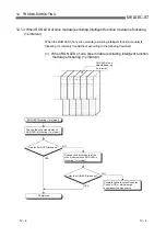
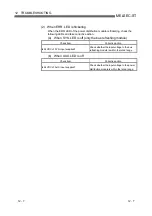
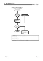
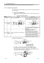
12.1.1 MELSEC-ST system checkup
Before starting slice module troubleshooting, check the description below.
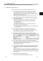
(1) Check that a proper number of slice modules are mounted.
Check whether 63 or less slice modules are used with the head module.
When intelligent function modules are mounted, check whether the number of the
intelligent function modules is 26 or less.
If the range is exceeded, the RUN LEDs of invalid slice modules are off.
(2) Check that the total number of occupied I/O points is within the
range of specifications.
Check whether the total number of occupied I/O points of the modules
comprising the MELSEC-ST system is within the range shown below.
CC-Link: 252 points
*1
PROFIBUS-DP: 256 points
If the range is exceeded, the RUN LEDs of invalid slice modules are off.
Refer to the head module manual for details.
1: The available points will decrease by two points for each additional power
distribution module.
(3) Check that slice modules are mounted on base modules
Before switching on the external power supplies of the MELSEC-ST system,
check whether slice modules are mounted on all base modules.
(4) Check the combination of slice modules and base modules.
Check whether the slice modules are mounted on the applicable base modules.
Module type
Reference section
Power distribution module
Chapter 5
I/O module
Chapter 7
Intelligent function module
Refer to intelligent function module manual.
(5) Check that the total slot width of slice modules is within 85cm.
Check whether the total slot width of the slice modules (without the head module)
comprising the MELSEC-ST system is within 85cm.
Refer to Chapter 3 for details.
(6) Check that the total 5VDC internal current consumption and total
24VDC current are within the capacity of the power distribution
modules.
Calculate the total 5VDC internal current consumption and total 24VDC current,
and check whether they are within the capacity of the power distribution modules.
Refer to Section 5.2.1 for the calculation of 5VDC internal current consumption
and 24VDC current.
(7) Check the error in the master station.
When an error occurs in master station, check the error to fix.
12
Summary of Contents for MELESEC-ST
Page 1: ......
Page 2: ......
Page 23: ...A 21 A 21 MEMO...
Page 114: ...10 22 10 22 10 MOUNTING AND INSTALLATION MELSEC ST MEMO...
Page 125: ...11 11 11 11 11 EMC AND LOW VOLTAGE DIRECTIVE MELSEC ST MEMO...
Page 163: ...Index 2 Index 2 MEMO Ind...
Page 165: ......
Page 166: ......


