App - 9 App - 9
APPENDICES
MELSEC-ST
Appendix 2 CC-Link
Appendix 2.1 I/O data
Appendix 2.1.1 Power distribution modules
The power distribution module does not occupy the areas for data transfer to and from
the head module.
Appendix 2.1.2 Input modules
The input module has the following areas for data transfer to and from the head
module.
The structure of each area will be explained in this section.
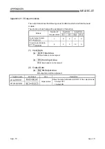
Input Data
Output Data
Module
Number of
occupied slices
Br
Wr
Bw
Ww
2-point input module
ST1X2-
1
2
0 0 0
4-point input module
ST1X4-
2
4 0 0 0
16-point input module
ST1X16-
8 16
0
0
0
(1) Input Data
(a) Br Bit Input Area
The Br Bit Input Area will be explained.
Target module
Bit Input
Item
Description
ST1X2-
Br.n to Br.n+1
ST1X4-
Br.n to Br.n+3
ST1X16-
Br.n to Br.n+15
Input status
Stores the input information (ON/OFF) of the input module.
0: Input OFF
1: Input ON
(b) Wr Word Input Area
Word input area is not occupied.
(2) Output Data
(a) Bw Bit Output Area
Bit output area is not occupied.
(b) Ww Bit Output Area
Word output area is not occupied.
Summary of Contents for MELESEC-ST
Page 1: ......
Page 2: ......
Page 23: ...A 21 A 21 MEMO...
Page 114: ...10 22 10 22 10 MOUNTING AND INSTALLATION MELSEC ST MEMO...
Page 125: ...11 11 11 11 11 EMC AND LOW VOLTAGE DIRECTIVE MELSEC ST MEMO...
Page 163: ...Index 2 Index 2 MEMO Ind...
Page 165: ......
Page 166: ......


