App - 19 App - 19
APPENDICES
MELSEC-ST
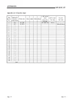
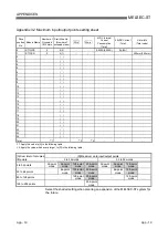
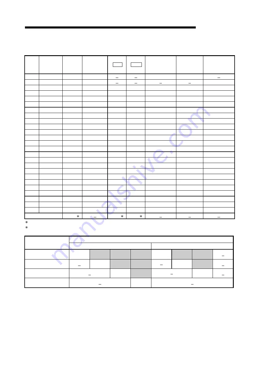
Appendix 3.2 Maximum input/output points setting sheet
Slice
position
No.
Module Name
Number of
Occupied
I/O Points
Start Slice No.
(Number of
occupied slices)
Wr.n
Ww.n
5VDC Internal
Current
Consumption
(Total)
24VDC Current
(Total)
Slot width
(Total value)
0 ST1H-PB
4
0(2)
0.530A(0.530A) 0A(0A)
1 ST1PSD
2
2(1)
25.2mm(25.2mm)
2
( )
3
( )
4
( )
5
( )
6
( )
7
( )
8
( )
9
( )
10
( )
11
( )
12
( )
13
( )
14
( )
15
( )
16
( )
17
( )
18
( )
19
( )
20
( )
21
( )
22
( )
23
( )
24
( )
Total
1
2
2
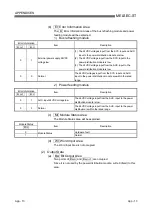
1: Apply this value to [A] in the following table.
2: Apply the value, whichever is larger, to [D] in the following table.
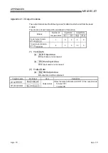
[D] Maximum word input/output points
[A] Sum total of occupied
I/O points
0 to 32 words
33 to 52 words
4 to 32 points
32-point
mode
64-point
mode
128-point
mode
256-point
mode
32-point
mode
64-point
mode
128-point
mode
33 to 64 points
64-point
mode
128-point
mode
256-point
mode
64-point
mode
128-point
mode
65 to 128 points
128-point
mode
256-point
mode
128-point
mode
129 to 256 points
256-point
mode
Select the shaded setting when planning an expansion of the MELSEC-ST system fpr
the future.
Summary of Contents for MELESEC-ST
Page 1: ......
Page 2: ......
Page 23: ...A 21 A 21 MEMO...
Page 114: ...10 22 10 22 10 MOUNTING AND INSTALLATION MELSEC ST MEMO...
Page 125: ...11 11 11 11 11 EMC AND LOW VOLTAGE DIRECTIVE MELSEC ST MEMO...
Page 163: ...Index 2 Index 2 MEMO Ind...
Page 165: ......
Page 166: ......

