Index - 1 Index - 1
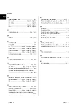
INDEX
[B]
Base module marker...................................... 8- 1
Bit Input.........................................App- 9, App-12
Bit Output...................................................App-18
Br ..................................................App- 9, App-12
Bw ................................................App-10, App-18
[C]
Coding Element....................................8- 2, 10- 9
[D]
DIN rail.................................................3-10, 10- 2
[E]
End brackets................................................... 8- 1
End plate......................................................... 8- 1
Er ...................................App-13, App-15, App-17
Error clear ......................App-14, App-16, App-18
Error Information ...........App-13, App-15, App-17
Ew ..................................App-14, App-16, App-18
External power supply..........................3- 4, 11- 9
[F]
Forced output test function .................... 9- 1, 9- 5
[ I ]
Information monitor function .................. 9- 1, 9- 5
Input Data .......................App- 9, App-12, App-15
Input response time setting function.............. 9- 4
Input response time setting monitor function
................................................................ 9- 1, 9- 5
[M]
Maximum number of connected modules ... 3- 10
Module Status ...............App-13, App-16, App-17
Mr...................................App-13, App-16, App-17
[O]
Online module change function ............. 9- 1, 9- 5
Operating status LEDs.........................5-12, 7-18
Output Data ...................App-13, App-16, App-18
Overload and overheat protection functions
....................................................................... 7-16
[P]
Performance specifications .................... 5- 1,7- 1
Power supply capacity check function .. 9- 1, 9- 5
Precautions for online module change .........3-12
[R]
Relay life.........................................................7-14
Response time ...............................................7-16
Restrictions on base modules .......................3-11
Restrictions on power distribution
modules..........................................................3-10
Restrictions on slot width...............................3-12
[S]
Setting of output status ...................................9- 4
Setting monitoring of output status........ 9- 1, 9- 5
Status monitor function .......................... 9- 1, 9- 5
[T]
Thermal protection.........................................7-16
[U]
UL certification-relevant restrictions ..............3-15
[W]
Wiring marker..................................................8- 1
Ind
Summary of Contents for MELESEC-ST
Page 1: ......
Page 2: ......
Page 23: ...A 21 A 21 MEMO...
Page 114: ...10 22 10 22 10 MOUNTING AND INSTALLATION MELSEC ST MEMO...
Page 125: ...11 11 11 11 11 EMC AND LOW VOLTAGE DIRECTIVE MELSEC ST MEMO...
Page 163: ...Index 2 Index 2 MEMO Ind...
Page 165: ......
Page 166: ......


