A - 15 A - 15
How to Read Manual (FOR PROFIBUS-DP)
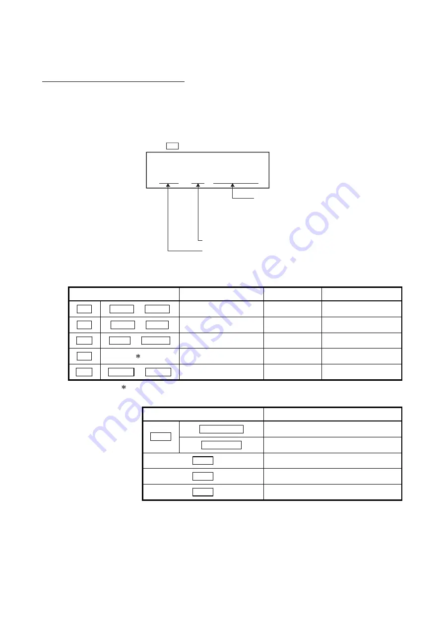
For PROFIBUS-DP, this manual explains each area for input data and output data
using the following symbols.
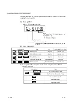
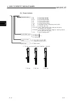
(1) Data symbol
<Example: Cr Command result area>
Cr. 0 (7-0)
Abbreviated data symbol
Detail data No.
Range
In the case of 1-word (16 bit) data, this shows the
corresponding range.
(0) : Shows 0 bit position
(7-0): Shows 0-7 bit range
For details of detail data No. and abbreviated data symbol, refer to
(2) and (3)
(2) Input send data
Data symbol
Area
Unit
Detail data No. notation
Br
Br.00
to Br.FF
Bit input area
1 bit/symbol
Hexadecimal
Er
Er.00
to ErFF
Error information area
1 bit/symbol
Hexadecimal
Mr
Mr.0
to Mr.127 Module status area
1 bit/symbol
Decimal
Cr
1
Command result area
1 word/symbol
Decimal
Wr
Wr.00
to Wr.33 Word input area
1 word/symbol
Hexadecimal
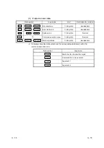
1: Following shows the data symbols and the corresponding detail areas within the
command result area.
Data symbol
Area
Cr.0 (15 - 8)
Command Execution Area
Cr.0
Cr.0 (7 - 0)
Start Slice No. of Execution Target
Cr.1
Executed Command No.
Cr.2 Response
Data
1
Cr.3 Response
Data
2
Summary of Contents for MELESEC-ST
Page 1: ......
Page 2: ......
Page 23: ...A 21 A 21 MEMO...
Page 114: ...10 22 10 22 10 MOUNTING AND INSTALLATION MELSEC ST MEMO...
Page 125: ...11 11 11 11 11 EMC AND LOW VOLTAGE DIRECTIVE MELSEC ST MEMO...
Page 163: ...Index 2 Index 2 MEMO Ind...
Page 165: ......
Page 166: ......


