3 - 4 3 - 4
3 SYSTEM CONFIGURATION
MELSEC-ST
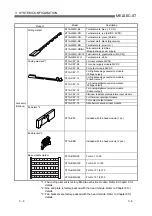
Device name
Description
Configuration condition
ST1H-BT
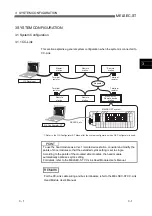
This module acts as a remote device station of a CC-Link
network to communicate with master station.
Head module
ST1H-PB
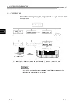
This module acts as a slave station of a PROFIBUS-DP
network to communicate with the master station.
Required (1 module must be
mounted)
Bus refreshing module
This module distributes 5VDC power necessary for the head
module and slice modules and 24VDC power necessary for
slice modules.
Required (1 module must be
mounted)
Must be increased when
power supply capacity is
insufficient.
Input module
Refer to Chapter 7 for details.
Used according to the system
configuration.
Output module
Refer to Chapter 7 for details.
Used according to the system
configuration.
Power feeding module
This module supplies 24VDC power necessary for slice
modules. It does not supply 5VDC power necessary for the
head module and slice modules.
Necessary when power supply
capacity is insufficient.
Intelligent function module
Various different intelligent function modules are available:
digital-analog conversion module, analog-digital conversion
module and thermocouple input module, platinum resistance
temperature input module and SSI absolute encoder input
module.
Used according to the system
configuration.
Base module for bus
refreshing module
Required (1 module must be
mounted)
Base module for input
module
Necessary when the input
module is mounted.
Base module for output
module
Necessary when the output
module is mounted.
Base module for power
feeding module
Necessary when the power
feeding module is mounted.
Base module for intelligent
function module
Used as base modules for the above slice modules. Refer to
Chapter 6 and Chapter 7 for details.
Necessary when the intelligent
function module is mounted.
End bracket
The end brackets are installed on the left side of the head
module and on the right side of the last end slice module
(installed into the end plate) to fix the slice modules between
them. The end brackets are used to make the base modules
unmovable under vibration, etc.
• For fixing the left side of the head module: 1 pc.
• For fixing the right end of the slice module: 1 pc. (Used with
the end plate)
Required (2 end brackets are
necessary: included with the
head module)
End plate
The end plate is installed to protect the terminals of the
rightmost base module from exposure.
Required (1 end plate is
necessary: included with the
head module)
GX Configurator-ST
Dedicated software for the MELSEC-ST system. (Slice
module status monitor, intelligent function module parameter
setting, online module change, etc. can be performed easily.)
Used as necessary.
RS-232 cable
Used to connect the personal computer installed with GX
Configurator-ST and the head module.
Model: QC30R2 (Mitsubishi Electric product) or SC-Q (Beijers)
Necessary when GX
Configurator-ST is used.
External power supply
(External SYS. power supply)
User-prepared product: Use an external isolated power
supply.
Refer to Section 11.1.4 for the recommended product.
Required
External power supply
(External AUX. power supply)
User-prepared product
Refer to Section 11.1.4 for the recommended product.
Required
Summary of Contents for MELESEC-ST
Page 1: ......
Page 2: ......
Page 23: ...A 21 A 21 MEMO...
Page 114: ...10 22 10 22 10 MOUNTING AND INSTALLATION MELSEC ST MEMO...
Page 125: ...11 11 11 11 11 EMC AND LOW VOLTAGE DIRECTIVE MELSEC ST MEMO...
Page 163: ...Index 2 Index 2 MEMO Ind...
Page 165: ......
Page 166: ......

