3 - 10 3 - 10
3 SYSTEM CONFIGURATION
MELSEC-ST
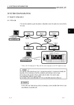
(1) Maximum number of connectable modules
The maximum number of slice modules that can be connected to one head
module is 63 (except the head module).
The number of head modules mountable on a field network changes depending
on the total input/output points of slice modules.
For details, refer to the Head Module User's Manual.
(2) Restrictions on power distribution modules
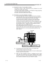
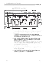
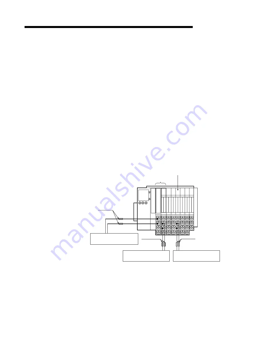
(a) Non-isolation type power distribution modules are used. Use an isolation
type external SYS. power supply. Use different external power supplies for
the external SYS. power supply and external AUX. power supply.
The power distribution modules do not have an overcurrent protection
function. If the load current is higher than the rated current (e.g. short
circuit) or the overcurrent continues to flow in the power distribution module
for a long time, this may cause smoke or ignition. To prevent this trouble,
provide fail-safe circuits, i.e., attach fuses outside the system. External
power supply must be turned ON/OFF externally.
When turning ON/OFF external power supply, an inrush current may run
during the power ON, which comes the external power supply to fail or shut
down. Refer to Section 11.1.4 for the recommended products (external
power supplies).
Fuses
Fuses
Fuses
External power supply
(External SYS. power supply)
Eternal power supply
(External AUX. power supply)
Eternal power supply
(External AUX. power supply)
Bus refreshing
module
Power feeding
module
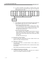
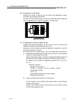
(b) On the right side of the head module, make sure to mount the bus
refreshing module to power the head module.
The bus refreshing module must be mounted on the base module designed
for power supply to the head module.
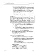
(c) Select the power distribution module by calculating the total current
consumption of the head module, I/O modules, Intelligent function modules
and others powered by the power distribution module. Refer to Chapter 5
for the selection and addition of the power distribution modules.
Summary of Contents for MELESEC-ST
Page 1: ......
Page 2: ......
Page 23: ...A 21 A 21 MEMO...
Page 114: ...10 22 10 22 10 MOUNTING AND INSTALLATION MELSEC ST MEMO...
Page 125: ...11 11 11 11 11 EMC AND LOW VOLTAGE DIRECTIVE MELSEC ST MEMO...
Page 163: ...Index 2 Index 2 MEMO Ind...
Page 165: ......
Page 166: ......

