A - 2 A - 2
[DESIGN PRECAUTIONS]
!
DANGER
Create an external fail safe circuit that will ensure the MELSEC-ST system operates safely,
even when the external power supply or the system fails.
Accident may occur due to output error or malfunctioning.
(1) The status of output changes depending on the setting of various functions that control the
output. Take sufficient caution when setting for those functions.
(2) Output may be kept ON or OFF due to malfunctions of an output element or its internal
circuits.
For signals which may cause a serious accident, configure an external monitoring.
!
CAUTION
Make sure to initialize the network system after changing parameters of the MELSEC-ST
system or the network system. If unchanged data remain in the network system, this may cause
malfunctions.
Do not install the control wires or communication cables together with the main circuit or power
wires. Keep a distance of 100 mm (3.94 inch) or more between them. Not doing so could result
in malfunctions due to noise.
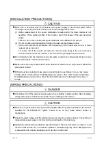
[INSTALLATION PRECAUTIONS]
!
CAUTION
Use the MELSEC-ST system in the general environment specified in the MELSEC-ST system
users manual. Using this MELSEC-ST system in an environment outside the range of the
general specifications could result in electric shock, fire, erroneous operation, and damage to or
deterioration of the product.
Mount the head module and base module on the DIN rail securely (one rail for one module)
referring to the MELSEC-ST system users manual and then fix them with end brackets.
Incorrect mounting may result in a drop of the module, short circuits or malfunctions.
Secure the module with several end brackets when using it in an environment of frequent
vibration. Tighten the screws of the end brackets within the specified torque range.
Undertightening can cause a drop, short circuit or malfunction. Overtightening can cause a
drop, short circuit or malfunction due to damage to the screw or module.
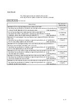
Summary of Contents for MELESEC-ST
Page 1: ......
Page 2: ......
Page 23: ...A 21 A 21 MEMO...
Page 114: ...10 22 10 22 10 MOUNTING AND INSTALLATION MELSEC ST MEMO...
Page 125: ...11 11 11 11 11 EMC AND LOW VOLTAGE DIRECTIVE MELSEC ST MEMO...
Page 163: ...Index 2 Index 2 MEMO Ind...
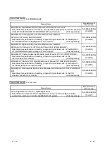
Page 165: ......
Page 166: ......


