3 - 13 3 - 13
3 SYSTEM CONFIGURATION
MELSEC-ST
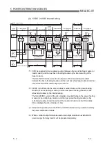
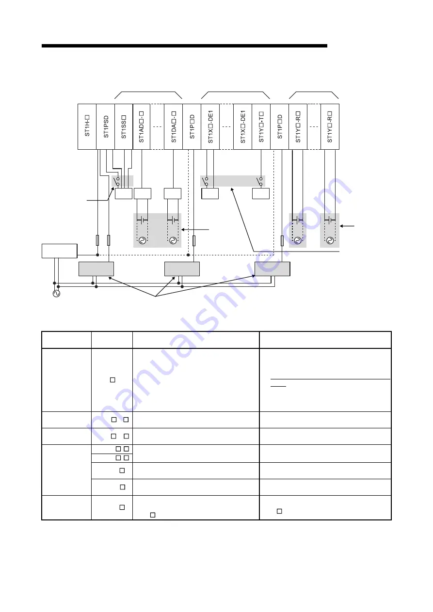
+24V
DC+/AC
DC-/AC
AUX.
AUX.
(SYS.)
AUX.
SYS.
(SYS.)
V+
V+
24G
Yn
100VAC
DC+/AC
DC-/AC
+24V
24G
DATA
CLK
*1
Intelligent function
modules
I/O modules
(excluding contact
output modules)
Contact output
modules
Fuse
A circuit for
power-off
should be
provided.
External AUX.
power supply
Fuse
Fuse
External AUX.
power supply
External AUX.
power supply
Separate external AUX. power supplies.
External device
disconnecting
means (switch)
should be provided.
External device
disconnecting
means (switch)
should be provided.
A circuit for
power-off
should be
provided.
External SYS.
power supply
External
device
External
device
External
device
External
device
External
device
(or I+)
(or I+)
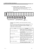
(c) External device connection and disconnection
Module Model
External device disconnection
(before module change)
External device connection
(after online module change)
Input module *1 ST1X -DE1
(1) When external device (3-wire type) is
connected to s24V, 24G, Xn (n
= 0 to F)
Disconnect the wiring of +24V.
(2) When external device (2-wire type) is
connected to s24V, Xn (n = 0 to
F)
No need to disconnect.
(1) When external device (3-wire type) is
connected to s24V, 24G, Xn (n =
0 to F)
Connect the wiring of 24V at each
point.
(2) When external device (2-wire type) is
connected to s24V, Xn (n = 0 to F)
No need to connect.
Transistor
output module
ST1Y -T
Disconnect the signal Yn (n = 0 to F).
Connect the wiring of Yn (n = 0 to F) and
external device.
Contact output
module
ST1Y -R
Switch off external power supply connected
to signals DC+/AC and DC-/AC.
Switch on the external power supply
connected to signals DC+/AC and DC-/AC.
ST1AD -
ST1DA -
Switch off the power of the external device
connected to signal V+ (or I+).
Switch on the power of the external device
connected to signal V+ (or I+).
ST1TD
Switch off the power of the external device
connected of signal TC+ and TC-.
Switch on the power of the external device
connected of signal TC+ and TC-.
Intelligent
function module
ST1RD
Switch off the power of the external device
connected to signals A, B and b.
Switch on the power of the external device
connected to signals A, B and b.
SSI absolute
encoder input
module
ST1SS
Disconnect the connection between the
external device and 24V of
ST1P D.
Connect the external device to 24V of
ST1P D.
*1: The maximum inrush current of 24V should be 2A/point (5ms). Also provide
in addition a disconnection circuit for each external connection.
A disconnecting circuit needs not be installed for the external device (2-wire type)
that is not connected to 24G of the input module.
Summary of Contents for MELESEC-ST
Page 1: ......
Page 2: ......
Page 23: ...A 21 A 21 MEMO...
Page 114: ...10 22 10 22 10 MOUNTING AND INSTALLATION MELSEC ST MEMO...
Page 125: ...11 11 11 11 11 EMC AND LOW VOLTAGE DIRECTIVE MELSEC ST MEMO...
Page 163: ...Index 2 Index 2 MEMO Ind...
Page 165: ......
Page 166: ......


