5 - 8 5 - 8
5 POWER DISTRIBUTION MODULES
MELSEC-ST
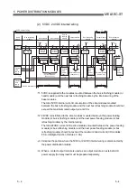
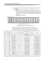
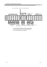
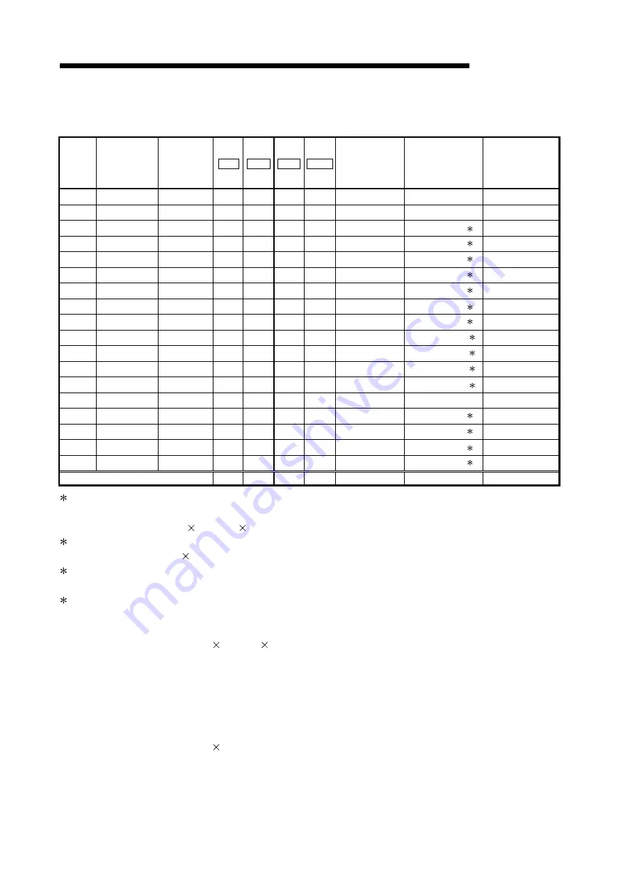
Calculate the total 24VDC current using the maximum I/O point setting sheet given in
Appendix 2 and 3.
Slice
position
No.
Start slice No.
(Number of
occupied slices)
Module name Br.n Bw.n Wr.n Ww.n
5VDC internal
current
consumption
(Total value)
24VDC current
(Total value)
Slot width
(Total value)
0 0(2)
ST1H-BT
- - - -
0.410A(0.410A)
0A(0A) -
1 2(1) ST1PSD
- - - -
-
- 25.2mm(25.2mm)
2 3(2)
ST1X4-DE1
4 - - -
0.095A(0.505A) 0.616A(0.616A) 1 12.6mm(37.8mm)
3 5(2)
ST1X4-DE1
4 - - -
0.095A(0.600A) 0.616A(1.232A) 1 12.6mm(50.4mm)
4 7(2)
ST1X4-DE1 4 - - - 0.095A(0.695A)
0.616A(1.848A) 1 12.6mm(63.0mm)
5 9(2)
ST1X4-DE1 4 - - - 0.095A(0.790A)
0.616A(2.464A) 1 12.6mm(75.6mm)
6 11(2)
ST1X4-DE1 4 - - - 0.095A(0.885A)
0.616A(3.080A) 1 12.6mm(88.2mm)
7 13(8)
ST1Y16-TE2
- 16 - -
0.150A(1.035A) 3.360A(6.440A) 2 100.8mm(189.0mm)
8 21(8)
ST1Y16-TE2 - 16 - -
0.150A(1.185A) 3.360A(9.800A) 2 100.8mm(289.8mm)
9 29(8)
ST1Y16-TE2 - 16 -
- 0.150A(1.335A)
3.360A(13.160A) 2 100.8mm(390.6mm)
10 37(8)
ST1Y16-TE2 - 16 -
- 0.150A(1.485A)
3.360A(16.520A) 2 100.8mm(491.4mm)
11 45(8)
ST1Y16-TE2 - 16 - -
0.150A(1.635A) 3.360A(19.880A) 2 100.8mm(592.2mm)
12 53(1)
ST1Y2-R2 - 2 - -
0.090A(1.725A) 0.035A(19.915A) 3 12.6mm(604.8mm)
13 54(1) ST1PSD - - - -
-
-
25.2mm(630.0mm)
14 55(2)
ST1DA2-V 4 4 - 2 0.095A(0.095A)
0.065A(0.065A) 4 12.6mm(642.6mm)
15 57(2)
ST1DA2-V 4 4 - 2 0.095A(0.190A)
0.065A(0.130A) 4 12.6mm(655.2mm)
16 59(2)
ST1DA2-V 4 4 - 2 0.095A(0.285A)
0.065A(0.195A) 4 12.6mm(667.8mm)
17 61(2)
ST1DA2-V 4 4 - 2 0.095A(0.380A)
0.065A(0.260A) 4 12.6mm(680.4mm)
Total 36
98
-
8
-
- -
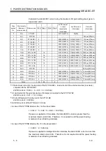
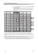
1: Rated input current (4 input points) of the ST1X4-DE1 + load current of the external devices (4 sensors)
connected to the ST1X4-DE1
24VDC current = 0.004 4 + 0.15 4 = 0.616(A)
2: Load current of the external devices (16 lamps) connected to the ST1Y16-TE2
24VDC current = 0.21 16 = 3.36(A)
3: Current flowing in the relay coil of the ST1Y2-R2
24VDC current = 0.035(A)
4: 24VDC current of the ST1DA2-V = 0.2(A)
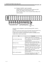
< In case of the ST1PSD listed as No.1 in the above table>
I = 0.616 5 + 3.36 5 + 0.035 = 19.915(A)
If power is supplied to I/O modules, the total 24VDC current is greater than the
maximum rated current 8.0A. Therefore, it is required to add the power feeding
modules (or bus refreshing modules).
< In case of the ST1PSD listed as No.13 in the above table>
I = 0.065 4 = 0.260 (A)
If power is supplied to intelligent function modules, the total 24VDC current is less than
the maximum rated current 3.0A. Therefore, it is not required to add the power feeding
modules (or bus refreshing modules).
Summary of Contents for MELESEC-ST
Page 1: ......
Page 2: ......
Page 23: ...A 21 A 21 MEMO...
Page 114: ...10 22 10 22 10 MOUNTING AND INSTALLATION MELSEC ST MEMO...
Page 125: ...11 11 11 11 11 EMC AND LOW VOLTAGE DIRECTIVE MELSEC ST MEMO...
Page 163: ...Index 2 Index 2 MEMO Ind...
Page 165: ......
Page 166: ......

