5 - 10 5 - 10
5 POWER DISTRIBUTION MODULES
MELSEC-ST
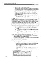
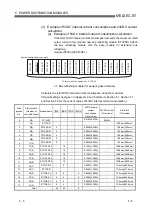
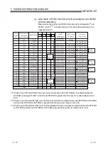
(c) Last check of 5VDC internal current consumption and 24VDC
current calculation
Make a last check of the total 5VDC internal current consumption
*
1
and
24VDC current
*
2
*
3
using the maximum I/O point setting sheet given in
Appendix 2 and 3.
Slice
position
No.
Start slice No.
(Number of
occupied slices)
Module name
Bw.n
Wr.n
Ww.n
5VDC internal
current
consumption
(Total value)
Br.n
24VDC current
(Total value)
Slot width
(Total value)
0
0(2)
ST1H-BT
-
0A(0A)
0.410A(0.410A)
-
-
-
-
1
2(1)
ST1PSD
25.2mm(25.2mm)
-
-
-
-
-
-
2
3(2)
ST1X4-DE1
12.6mm(37.8mm)
0.616A(0.616A)
0.095A(0.505A)
-
-
-
4
3
5(2)
ST1X4-DE1
12.6mm(50.4mm)
0.616A(1.232A)
0.095A(0.600A)
-
-
-
4
4
7(2)
ST1X4-DE1
12.6mm(63.0mm)
0.616A(1.848A)
0.095A(0.695A)
-
-
-
4
5
9(2)
ST1X4-DE1
12.6mm(75.6mm)
0.616A(2.464A)
0.095A(0.790A)
-
-
-
4
6
11(2)
ST1X4-DE1
12.6mm(88.2mm)
0.616A(3.080A)
0.095A(0.885A)
-
-
-
4
7
13(8)
ST1Y16-TE2
100.8mm(189.0mm)
3.360A(6.440A)
0.150A(1.035A)
-
-
16
-
8
54(1)
ST1PDD
12.6mm(201.6mm)
-
0.060A(1.095.A)
-
-
-
-
9
55(8)
ST1Y16-TE2
100.8mm(289.8mm)
3.360A(3.360A)
0.150A(1.245A)
-
-
16
-
10
63(8)
ST1Y16-TE2
100.8mm(390.6mm)
3.360A(6.720A)
0.150A(1.395A)
-
-
16
-
11
71(1)
ST1PDD
12.6mm(201.6mm)
-
0.060A(1.455A)
-
-
-
-
12
72(8)
ST1Y16-TE2
100.8mm(491.4mm)
3.360A(3.360A)
0.150A(1.605A)
-
-
16
-
13
80(8)
ST1Y16-TE2
100.8mm(592.2mm)
3.360A(6.720A)
0.150A(1.755A)
-
-
16
-
14
88(1)
ST1Y2-R2
12.6mm(604.8mm)
0.035A(6.755A)
0.090A(1.845A)
-
-
2
-
15
89(1)
ST1PSD
25.2mm(630.0mm)
-
-
-
-
-
-
16
90(2)
ST1DA2-V
12.6mm(642.6mm)
0.065A(0.065A)
0.095A(0.095A)
2
-
4
4
17
92(2)
ST1DA2-V
12.6mm(655.2mm)
0.065A(0.130A)
0.095A(0.190A)
2
-
4
4
18
94(2)
ST1DA2-V
12.6mm(667.8mm)
0.065A(0.195A)
0.095A(0.285A)
2
-
4
4
19
96(2)
ST1DA2-V
12.6mm(680.4mm)
0.065A(0.260A)
0.095A(0.380A)
2
-
4
4
Total
-
-
-
8
-
98
36
Total
6.440A
Total
6.720A
*2
Total
6.755A
Total
0.260A
*3
Total
1.845A
*1
Total
0.380A
*1
*2
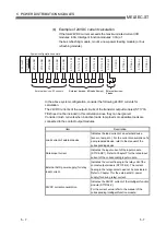
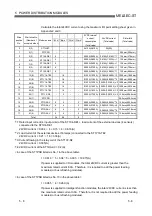
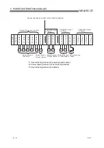
1: Check to see if the total 5VDC internal current consumption of the I/O modules mounted between the
ST1PSD (including ST1H-BT) and the next ST1PSD is greater than the maximum rated output current
2.0A.
2: Check to see if the total 24VDC current of the slice modules mounted between the ST1PDD (or ST1PSD)
and the next ST1PDD (or ST1PSD) is greater than the maximum rated current 8.0A.
3: Check to see if the total 24VDC current of the intelligent function modules mounted between the ST1PDD
(or ST1PSD) and the next ST1PDD (or ST1PSD) is greater than maximum rated current 3.0 A.
Summary of Contents for MELESEC-ST
Page 1: ......
Page 2: ......
Page 23: ...A 21 A 21 MEMO...
Page 114: ...10 22 10 22 10 MOUNTING AND INSTALLATION MELSEC ST MEMO...
Page 125: ...11 11 11 11 11 EMC AND LOW VOLTAGE DIRECTIVE MELSEC ST MEMO...
Page 163: ...Index 2 Index 2 MEMO Ind...
Page 165: ......
Page 166: ......


