7 - 2 7 - 2
7 I/O MODULES
MELSEC-ST
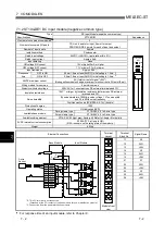
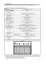
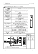
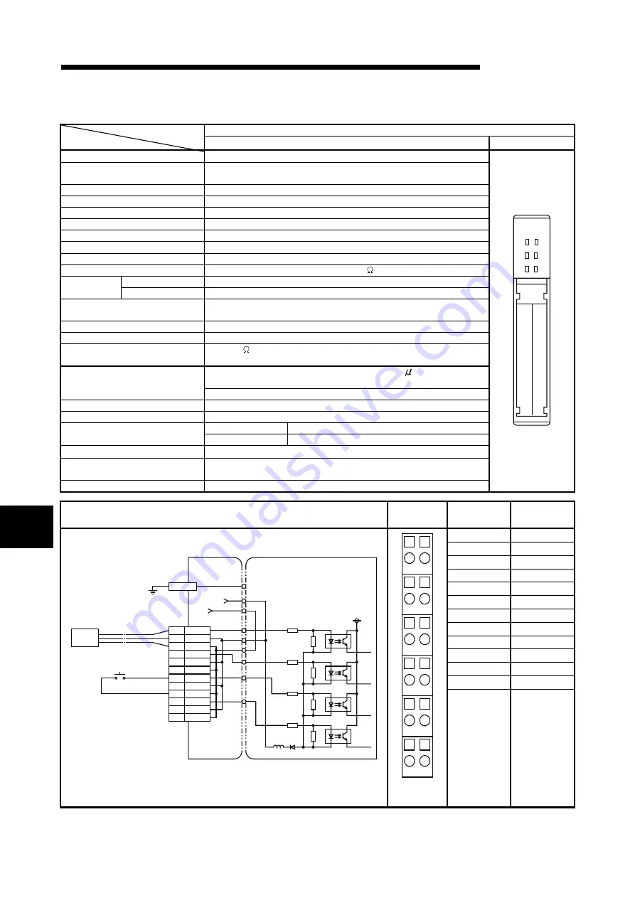
7.1.2 ST1X4-DE1 DC input module (negative common type)
DC Input Module (negative common type)
Type
Specifications
ST1X4-DE1
Appearance
Number of occupied slice modules
2
Number of occupied I/O points
CC-Link: 4 points for input, 0 point for output
PROFIBUS-DP: 4 points for each of input and output
Number of input points
4 points
Isolation method
Photocoupler
Rated input voltage
24VDC (+20/-15%, ripple ratio within 5%)
Rated input current
Approx. 4mA
Input derating
None
ON voltage/ON current
19V or higher/3mA or higher
OFF voltage/OFF current
11V or lower/1.7mA or lower
Input resistance
Approx. 5.6k
OFF to ON
0.5ms/1.5ms or less (24VDC) Initial setting is 1.5ms.
*1
Response
time
ON to OFF
0.5ms/1.5ms or less (24VDC) Initial setting is 1.5ms.
*1
24VDC maximum current
2A (total current of signal "+24V")
(During online module change, maximum inrush current is 2A/point (5ms))
Wiring method for common
4 points/common
Dielectric withstand voltage
500VAC for 1 minute across DC external terminals and FG
Insulation resistance
10M or larger by insulation resistance tester across DC external
terminals and FG
By noise simulator of 500Vp-p noise voltage, 1
s noise width
and 25 to 60Hz noise frequency
Noise durability
First transient noise IEC61000-4-4: 1kV (bundle)
Protection of degree
IP20
Operating status
ON indication (LED)
Spring clamp type
ST1B-S6X4 2 to 3-wire type
Available base module
Screw clamp type
ST1B-E6X4 2 to 3-wire type
Available coding element
ST1A-CKY-02 (light gray) (factory-fit) Refer to Chapter 8 for details.
5VDC internal current consumption
0.095A (TYP. all points ON)
(0.10A is shown on the rating plate of the module.)
Weight 0.03kg
11
21
ST1X4
-DE1
14
24
RUN
ERR.
External Connections
Terminal
Layout
Terminal
Block No.
Signal Name
11 X0
12 24G
13 +24V
14 X2
15 24G
16 +24V
21 X1
22 24G
23 +24V
24 X3
25 24G
26 +24V
11
X0
12
24G
13
+24V
14
15
16
21
22
*3
24G
*3
+24V
*2
*3: Connection from the power distribution module.
23
24
25
26
X2
24G
+24V
X1
24G
+24V
X3
24G
+24V
Base Module
Input Module
3-wire
Sensor
*2:
This FG terminal is not connected.
(Grounded at the FG contact of the base module for power distribution module.)
11
21
12
22
13
23
14
24
15
25
16
26
Module front
view
*1: For response time of an input module, refer to Chapter 9.
7
Summary of Contents for MELESEC-ST
Page 1: ......
Page 2: ......
Page 23: ...A 21 A 21 MEMO...
Page 114: ...10 22 10 22 10 MOUNTING AND INSTALLATION MELSEC ST MEMO...
Page 125: ...11 11 11 11 11 EMC AND LOW VOLTAGE DIRECTIVE MELSEC ST MEMO...
Page 163: ...Index 2 Index 2 MEMO Ind...
Page 165: ......
Page 166: ......


