7 - 12 7 - 12
7 I/O MODULES
MELSEC-ST
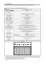
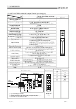
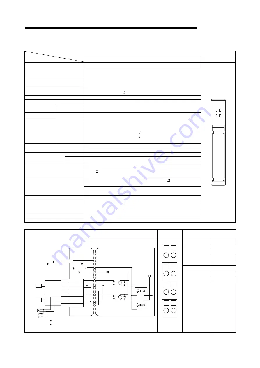
7.2.6 ST1Y2-R2 Contact Output Module
Contact Output Module
Type
Specifications
ST1Y2-R2 Appearance
Number of occupied slice modules
1
Number of occupied I/O points
CC-Link: 0 point for input, 2 points for output
PROFIBUS-DP: 2 points for each of input and output
Number of output points
2 points
Isolation method
Photocoupler
Rated switching voltage, current
24VDC 2A (resistive load)
240VAC 2A (cos =1)
/point, 4A/common
Minimum switching load
5VDC 1mA
Maximum switching load
264VAC 125VDC
OFF to ON
10ms or less
Response time
ON to OFF
12ms or less
Wiring method for common
2 points/common
Mechanical
20 million times or more
Rated switching voltage/current load
More than 100 thousand times or more
Life
Electrical
200VAC 1.5A, 240VAC 1A (cos = 0.7) 100 thousand times or more
200VAC 1A, 240VAC 0.5A (cos = 0.35) 100 thousand times or more
24VDC 1A, 100VDC 0.1A (L/R = 7ms) 100 thousand times or more
Maximum switching frequency
3600 times/hour
Surge suppressor
No
Voltage
24VDC (+20/-15%, ripple ratio within 5%)
External power supply
for driving relay
Current
35mA or less (24VDC, when all points are ON)
Fuse No
Dielectric withstand voltage
2830VAC rms/3 cycles (altitude 2000m (6557.38ft.))
Insulation resistance
10M or larger by insulation resistance tester across external terminals
and FG
By noise simulator of 1500Vp-p noise voltage, 1 s noise width
and 25 to 60Hz noise frequency
Noise durability
First transient noise IEC61000-4-4: 1kV (bundle)
Protection of degree
IP20
Operating status
ON indication (LED)
Spring clamp type
ST1B-S4IR2 2-wire type
Available base module
Screw clamp type
ST1B-E4IR2 2-wire type
Available coding element
ST1A-CKY-17 (brown) (factory-fit) Refer to Section 8 for details.
5VDC internal current consumption
0.090A (TYP. all points ON)
Weight 0.04kg
11
21
ST1Y2
-R2
RUN
ERR.
External Connections
Terminal
Layout
Terminal Block
No.
Signal Name
11 Y0
12 DC+/AC
13 DC-/AC
14 COM
21 Y1
22 DC+/AC
23 DC-/AC
24 COM
100/200VAC
24G
+24V
Base Module
Output Module
L
L
11
12
13
14
21
22
23
24
Y0
DC+/AC
DC-/AC
COM
Y1
DC+/AC
DC-/AC
COM
RA
RA
24VDC
1: Grounded to the DIN rail via the FG contact of the base module.
2: Connection from power distribution module.
1
2
2
11
21
12
22
13
23
14
24
Module front
view
Summary of Contents for MELESEC-ST
Page 1: ......
Page 2: ......
Page 23: ...A 21 A 21 MEMO...
Page 114: ...10 22 10 22 10 MOUNTING AND INSTALLATION MELSEC ST MEMO...
Page 125: ...11 11 11 11 11 EMC AND LOW VOLTAGE DIRECTIVE MELSEC ST MEMO...
Page 163: ...Index 2 Index 2 MEMO Ind...
Page 165: ......
Page 166: ......


