7 - 22 7 - 22
7 I/O MODULES
MELSEC-ST
7.4 Part Names
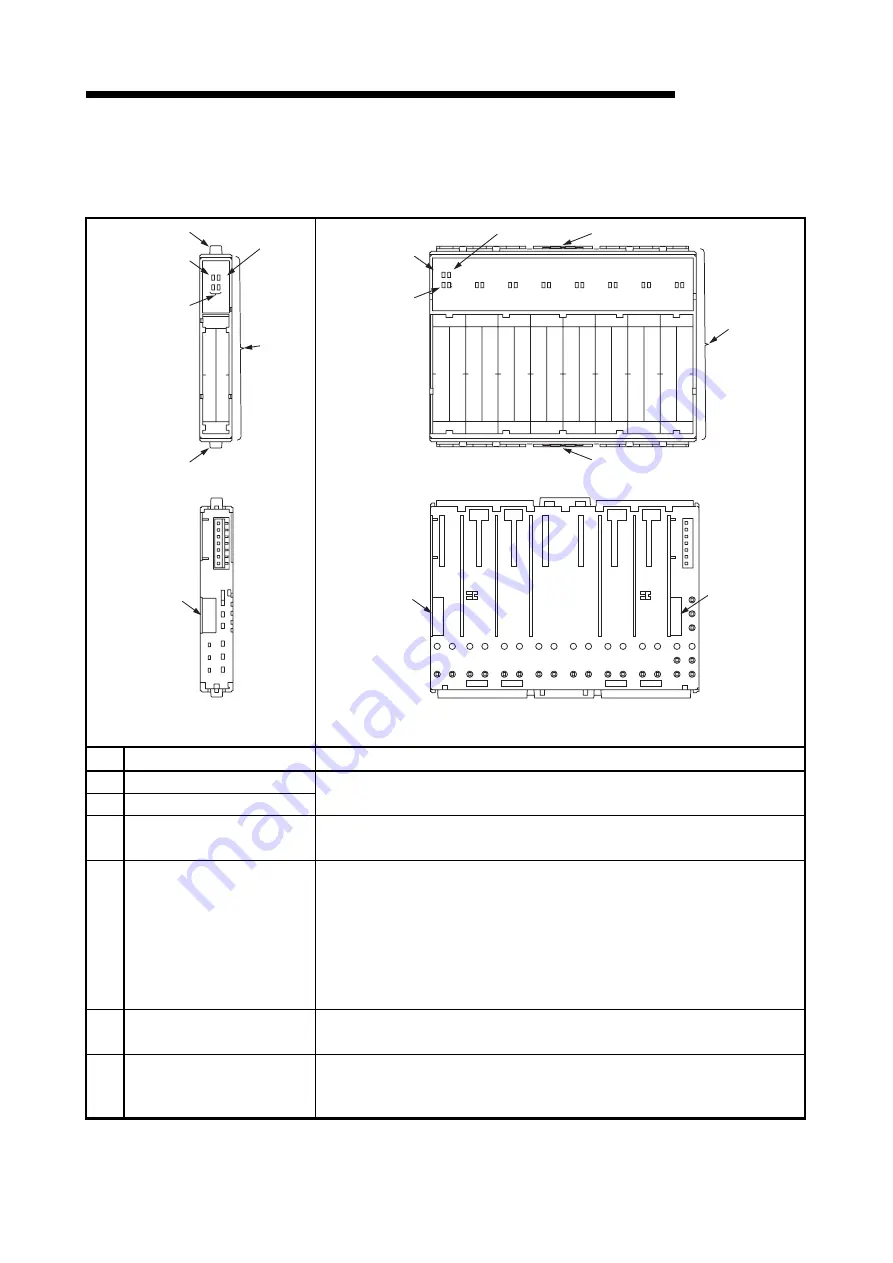
This section explains the part names of the I/O modules.
-TPE3
ST1Y2
ERR.
RUN
21
11
5)
5)
4)
3)
2)
1)
-TPE3
ST1Y16
ERR.
RUN
11
21
31
41
51
61
71
81
91
101
111
121
131
141
151
161
5)
4)
3)
2)
1)
5)
Front view
Front view
6)
6)
6)
Rear view
Rear view
1 slot width
8 slot width
No. Name
Application
1) RUN
LED
2) ERR.
LED
Refer to Section 7.4 (1).
3)
I/O status LEDs
(Example: 11 to 162)
Indicate whether the inputs/outputs are ON or OFF. The LED is lit when the
corresponding input/output is ON, and is unlit when it is OFF.
4) Faceplate
• The I/O module statuses in above 1) to 3) are indicated by the LEDs.
• The diagram of wiring to base module is printed on the surface. When checking
the wring diagram, remove the symbol label.
• The I/O module types are color-coded as indicated below.
Input module: Light gray
Transistor output module: Orange
Contact output module: Brown
5)
Slice module fixing hooks
(both ends)
Hooks provided to mount/remove the I/O module to/from the base module.
Hold down the mounting/removing hooks at both ends and remove the module.
6) Coding
element
Provided to prevent the I/O module from being improperly inserted into the base
module. The I/O module can be inserted only when the coding element of the
base module matches that of the I/O module. (Refer to Chapter 8 for details.)
Summary of Contents for MELESEC-ST
Page 1: ......
Page 2: ......
Page 23: ...A 21 A 21 MEMO...
Page 114: ...10 22 10 22 10 MOUNTING AND INSTALLATION MELSEC ST MEMO...
Page 125: ...11 11 11 11 11 EMC AND LOW VOLTAGE DIRECTIVE MELSEC ST MEMO...
Page 163: ...Index 2 Index 2 MEMO Ind...
Page 165: ......
Page 166: ......


