5Maintenance and Inspection
Maintenance and inspection procedures
5-71
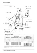
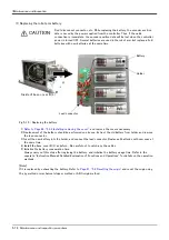
(4) Inspection and maintenance of J3 axis timing belt
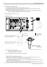
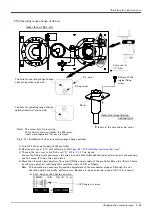
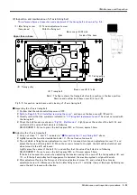
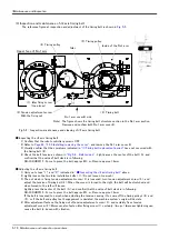
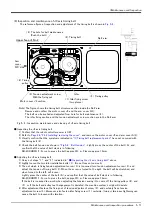
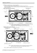
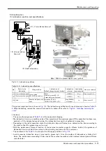
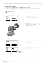
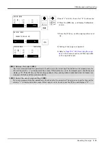
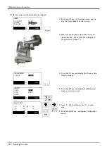
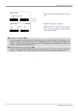
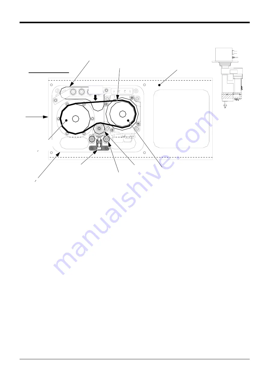
The reference figure at inspection and adjustment of the timing belt is shown in
.
Fig.5-6 : Inspection, maintenance and cleaning of J3 axis timing belt
■ Inspecting the J3 axis timing belt
1) Confirm that the robot controller power is OFF.
2) Refer to
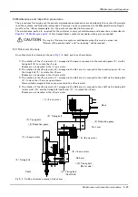
Page 66, "5.3.2 Installing/removing the cover"
, and remove the motor cover J3 and arm cover A(3).
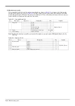
3) Visually confirm that the symptoms indicated in
"(1)Timing belt replacement period"
have not occurred with
the timing belt <2>.
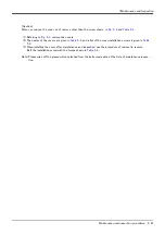
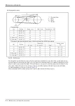
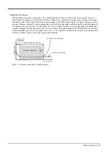
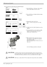
4) Check the belt tension as shown in
. Lightly press the center of the belt <A>, and
confirm that the value of belt slack is in following.
RH-3SDHR3515 : Force to press the belt: apprpx.3N ・ m, Flexure: approx.1.2mm
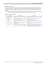
■ Adjusting the J3 axis timing belt
and
indicated in
" ■ Inspecting the J3 axis timing belt"
above.
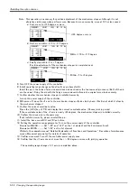
2) Lightly loosen the two idler installation bolts <1>. (Do not loosen too much.)
3) The nut which is fixing tension adjustment screw <3> is loosened, turn tension adjustment screw <3>, and
adjust the tension of timing belt <2>. When the screw is turned to the right, the belt will be stretched, and
when turned to the left, will loosen.
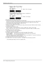
Lightly press the center of the belt <A>, and confirm that the value of belt slack is in following.
RH-3SDHR3515 : Force to press the belt: apprpx.3N ・ m, Flexure: approx.1.2mm
If the belt is loosened too much when adjusting the tension causing it to come off the timing pulleys <4> and
<5>, or if the belt and pulley teeth engagement is deviated, the machine system's origin will deviate
4) After adjustment fastens the fixing nut of tension adjustment screw <3>, and certainly fixes tension
adjustment screw <3>. Moreover, also fasten idler fixing screw <1> certainly. (two pc.) Improper tightening can
cause the belt to loosen with vibration.
Note) The figure shows the timing belt structure section inside the No.2 arm.
Remove and confirm the motor cover J3 and the arm cover A(3).
The belt can be pushed and adjusted from hole for belt maintenance <6>.
The idler fixing section and the tension adjustment screw section are in the No.2 arm.
Arm
cover
A(3) side
Idler
<2> Timing belt
<5> Timing pulley
<6> The hole for belt maintenance
(Push the belt)
No.2 arm
<A>
<3>Tension adjustment screw
With the fixing nut
<1> Idler fixing screw
(two places)
Upper face of No.2
<4> Timing
pulley
Motor cover J3 section

