2-16
Spare wiring
2Unpacking to Installation
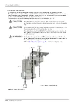
2.3.2 Base area
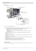
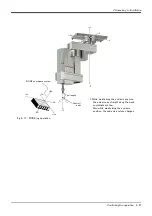
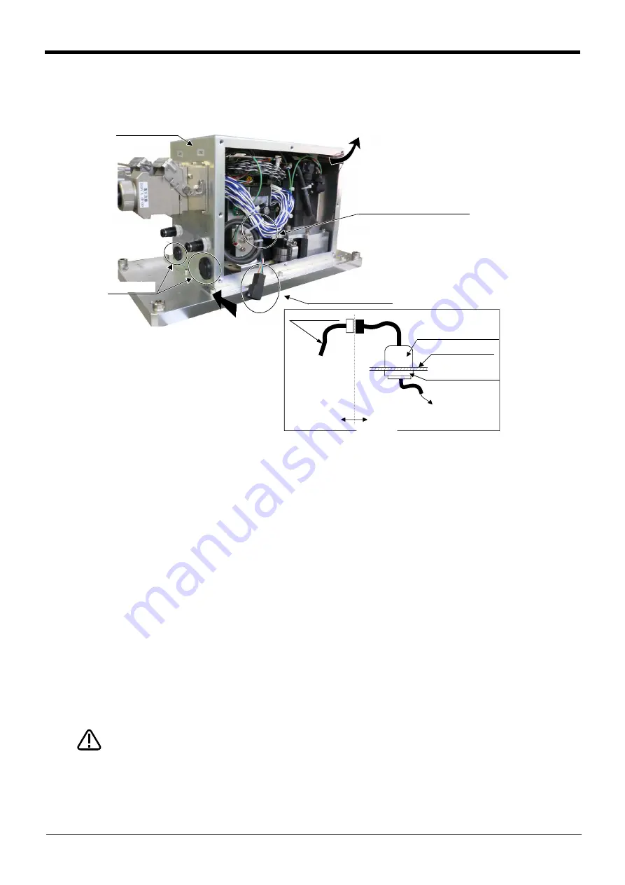
1) Remove the base cover B (R).
Fig.2-8 : Pull out spare wiring(Base area)
2) The spare wiring (ADD: coiled ) preinstalled in the robot arm has connector. The spare wiring (ADD) prein
-
stalled in the robot arm has connector. Please prepare the following of the customer.
・ The cable (calls the "cable for spare wiring connection" below)
・ Connector
・ The cable clamp for fixing the cable for spare wiring connection (OA-W1608 : Product by OHM
ELECTRIC CO., LTD)
(The cable is AWG#27 (0.1mm
2
). Refer to the "standard specification document" for detail of the
connector.)
3) Remove the base cover B (L).
4) Confirm spare wiring (ADD). Since spare wiring is bundled in the cable tie, if length is necessary, cut the
cable tie.
5) Remove the grommet on the base.
6) Install the connector after letting the cable for spare wiring connection of customer preparation pass to the
cable clamp.
7) Fixing the cable clamp securely to the hole which removed the grommet.
8) Connect the cable for spare wiring connection to the spare wiring.
9) Install the base cover B (L) as before. Be careful not to catch any the cables.
When pulling out spare wiring, keep big power from being added to the cable, the air
hose.
ベースカバーB(R)を外す
予備配線(ADD)
結束バンド
(長さ不足時は解いてください)
グロメット
ベース部
ツール・センサ等へ接続
お客様配線側
ロボット本体側
予備配線
ケーブルクランプ
(お客様ご準備品)
ベース部
ロックナット
(お客様ご準備品)
矢視A
A
Base section
Grommet
Remove base cover B (R)
Cable tie
(If length is short cut it.)
Spare wire (ADD)
Spare wiring
Cable clamp
(Customer preparation)
No.2 arm cover
Lock nut
(Customer preparation)
Connect with the tool sensor etc.
Robot arm side
Customer wiring side
View A
CAUTION


