6-105
Safety
6Safety
6.1.7 Examples of safety measures
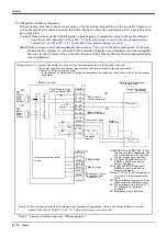
Two emergency-stop input circuits are prepared on the user wiring terminal block of the controller. Create a cir
-
cuit as shown below for safety measures. In addition, the figure shows the normal state which is not in the emer
-
gency stop state.
[Caution] Since we have omitted the information in part because of explanation, there is the section different
from the product. Also refer to
Page 109, "(1) External emergency stop connection [supplementary
and
Page 50, "3.6.1 Connection of the external emergency stop"
.
[Note] In the emergency-stop related wiring by the customer, if the coil (is not the contact points) of the relay
prepared by the customer is connected to the controller, please be sure to implement the measure against
the noise by the customer in the coil section. And, please also take the lifetime of noise suppression parts
into consideration.
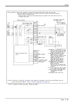
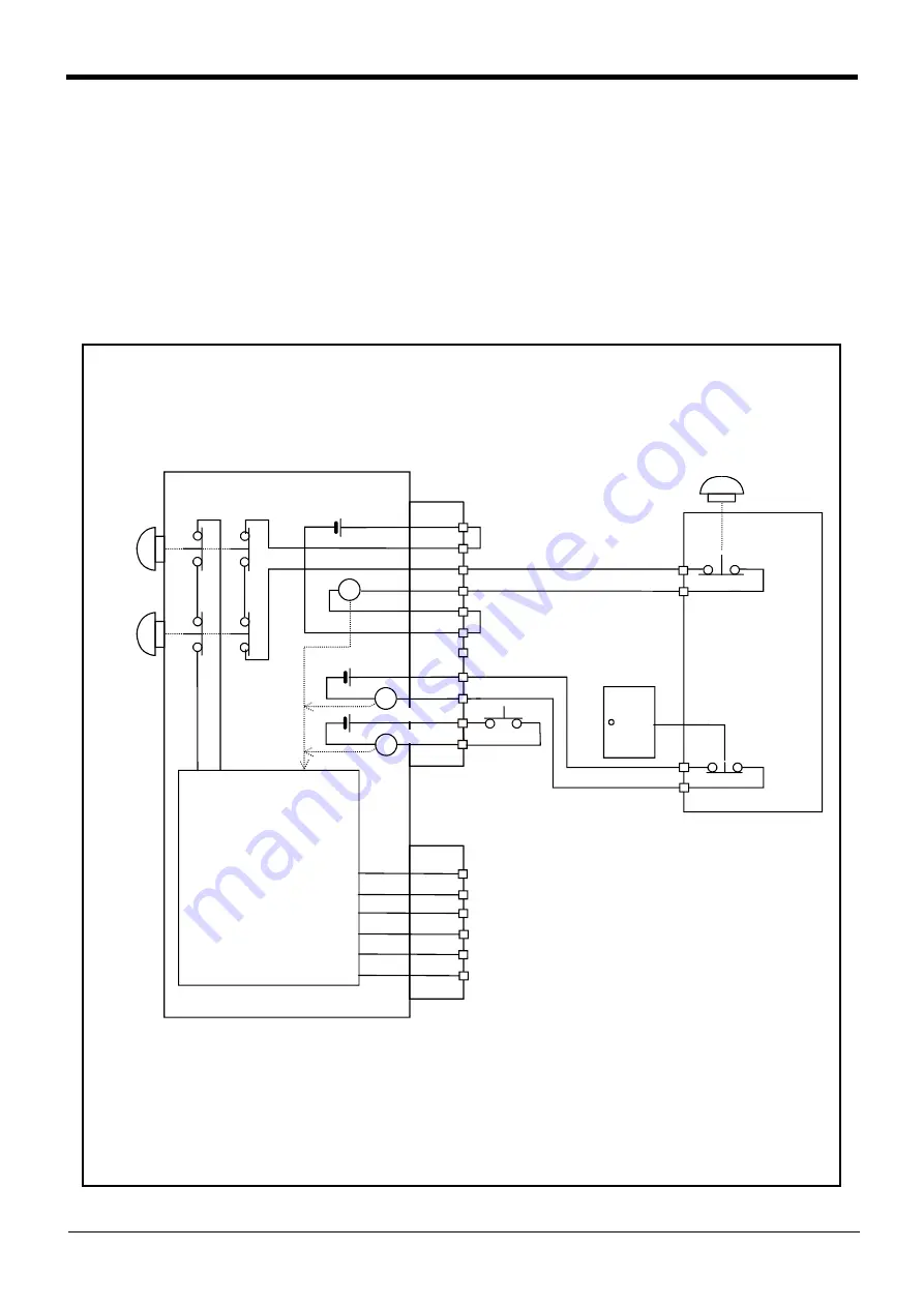
Fig.6-1 : Example of safety measures (Wiring example 1)
1A/1B
2A/2B
3A/3B
4A/4B
5A/5B
6A/6B
8A/8B
9A/9B
1A/1B
2A/2B
3A/3B
4A/4B
5A/5B
6A/6B
EMGIN1/2
EMGOUT1/2
付加軸用コンタクタ
コントロール出力
内部非常停止回路
ロボットコントローラ
短絡(出荷時短絡済)
非常停止スイッチ
(2接点タイプ)
エラー出力
モード出力
周辺装置
TB非常停止
ボタン
OP非常停止
ボタン
}
RA
RA
RA
短絡(出荷時短絡済)
7A/7B
}
}
10A/10B
11A/11B
ロボットコント
ローラ内電源 24V
ドアスイッチ入力
安全柵のドア
イネーブリング
デバイス
[Caution] Since we have omitted the information in part because of explanation, there is the section different from the
product. Also refer to
Page 52, "Fig.3-13 : External emergency stop connection"
<Wiring example 1>: Connect the emergency stop switch of peripheral equipment to the robot controller.
The power supply for emergency stop input uses the power supply in the robot controller.
<Operation of the emergency stop>
If the emergency stop switch of peripheral equipment is pushed, the robot will also be in the emergency
stop state.
*1)EMGIN1/2, and EMGOUT1/2 have
the two terminals separately, and
show that they are the two lines.
Always connect the two lines.
*2) 1A/1B, and 2A/2B terminal of
EMGIN is short-circuited at
factory shipments.
*3)5A/5B, and 6A/6B terminal of
EMGIN is short-circuited at
factory shipments.
Notes) If "*2" and "*3" are removed,
it will be in the emergency stop
state.
*4) The emergency stop button of the
robot controller operation panel.
*5) The emergency stop button of T/
B connected to the robot
controller.
*6) Emergency stop input relay.
*1)
*2)
*3)
*4)
*5)
*6)
Robot controller
Short circuit
(short-circuited)
Enabling
device
Door switch input
Short circuit
(short-circuited)
Power supply in the
robot controller 24V
Emergency stop switch
(2- contact type)
Peripheral
equipment
Safety
fence door
OP
Emer
-
gency
stop
button
TB
Emer
-
gency
stop
button
Internal emergency stop
circuit
Error output
Mode output
Contactor control
output for addi
-
tional axes
Summary of Contents for MELFA RV-2SD Series
Page 2: ......
Page 122: ......
Page 123: ......
Page 124: ......
Page 125: ......
Page 126: ......
Page 127: ......
Page 128: ......
Page 129: ......
Page 130: ......
Page 131: ......
Page 132: ......
Page 133: ......
Page 134: ......
Page 135: ......
Page 136: ......
Page 137: ......
Page 138: ......
Page 139: ......
Page 140: ......
Page 141: ......
Page 142: ......
Page 143: ......
Page 144: ......
Page 145: ......
Page 146: ......
Page 147: ......
Page 148: ......
Page 149: ......


