3Controller
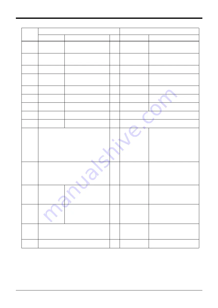
Dedicated input/output 3-51
IODATA
Note2)
Numeric value input
(start No., end No.)
Used to designate the program
name, override value., mechanism
value.
L
Numeric value output
(start No., end No.)
Used to output the program name,
override value., mechanism No.
PRGOUT
Program No. out
-
put request
Requests output of the program
name.
E
Program No. output
signal
Outputs that the program name is
being output to the numeric value out
-
put signal.
LINEOUT
Line No. output
request
Requests output of the line No.
E
Line No. output signal
Outputs that the line No. is being out
-
put to the numeric value output signal.
OVRDOUT
Override value out
-
put request
Requests the override output.
E
Override value out
-
put signal
Outputs that the override value is being
output to the numeric value output sig
-
nal.
ERROUT
Error No. output
request
Requests the error No. output.
E
Error No. output sig
-
nal
Outputs that the error No. is being out
-
put to the numeric value output signal.
JOGENA
Jog valid input sig
-
nal
Validates jog operation with the
external signals
E
Jog valid output sig
-
nal
Outputs that the jog operation with
external signals is valid.
JOGM
Jog mode input 2-
bit
Designates the jog mode.
L
Jog mode output 2-
bit
Outputs the current jog mode.
JOG+
Jog feed + side for
8-axes
Requests the + side jog operation.
L
None
JOG-
Jog feed - side for
8-axes
Requests the - side jog operation.
L
None
HNDCNTL1
:
HNDCNTL3
None
Mechanism 1 hand
output signal status
:
Mechanism 3 hand
output signal status
Mechanism 1: Outputs the status of
general-purpose outputs
900 to 907.
Mechanism 2: Outputs the status of
general-purpose outputs
910 to 917.
Mechanism 3: Outputs the status of
general-purpose outputs
920 to 927.
HNDSTS1
:
HNDSTS3
None
Mechanism 1 hand
input signal status
:
Mechanism 3 hand
input signal status
Mechanism 1: Outputs the status of
hand inputs 900 to 907.
Mechanism 2: Outputs the status of
hand inputs 910 to 917.
Mechanism 3: Outputs the status of
hand inputs 920 to 927.
HNDERR1
:
HNDERR3
Mechanism 1 hand
error input signal
:
Mechanism 3 hand
error input signal
Requests the hand error occur
-
rence.
L
Mechanism 1 hand
error output signal
:
Mechanism 3 hand
error output signal
Outputs that a hand error is occurring.
AIRERR1
:
AIRERR3
Pneumatic pressure
error 1 input signal
:
Pneumatic pressure
error 3 input signal
Request the pneumatic pressure
error occurrence.
L
Pneumatic pressure
error 1 output signal.
:
Pneumatic pressure
error 3 output signal.
Outputs that a pneumatic pressure
error is occurring.
M1PTEXC
:
M3PTEXC
None
L
Maintenance parts
replacement time
warning signal
Outputs that the maintenance parts
have reached the replacement time.
USER
-
AREA
Note3)
None
User-designated area
8-points
Outputs that the robot is in the user-
designated area.
Note1) The level indicates the signal level.
L: Level signal → The designated function is validated when the signal is ON, and is invalidated when the sig
-
nal is OFF.
E: Edge signal → The designated function is validated when the signal changes from the OFF to ON state, and
the function maintains the original state even when the signal then turns OFF.
Note2) Four elements are set in the order of input signal start No., end No., output signal start No. and end No.
Note3) Up to eight points can be set successively in order of start output signal No. and end output signal No.
Parameter
name
Input
Note1)
Output
Name
Function
Level
Name
Function


