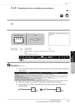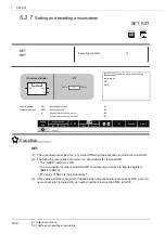
5.3 Output Instructions
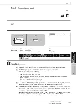
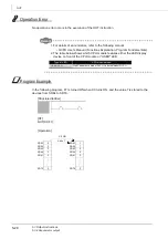
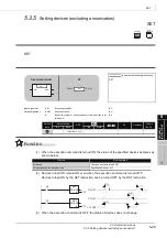
5.3.9 Bit device output inversion
5-41
5
SE
Q
U
EN
C
E
INSTRUCTION
S
FF
FF
Program
E
xam
pl
e
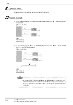
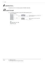
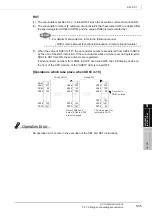
(1) In the following program, the output of Y10 is inverted when X9 turns ON.
[Structured ladder]
[ST]
FF(X9,Y10);
[Timing chart]
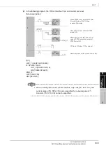
(2) In the following program, b10 (bit 10) of D10 is inverted when X0 turns ON.
[Structured ladder]
[ST]
FF(X0,D10.A);
[Timing chart]
O
N
X
9
Y1
0
O
N
O
FF
O
FF
ON
X
0
b1
0 o
f
D
1
0
OFF
0
1
0
Summary of Contents for MELSEC Q Series
Page 1: ...Structured Programming Manual Mitsubishi Programmable Controller QCPU Common Instructions ...
Page 2: ......
Page 14: ...A 12 MEMO ...
Page 340: ...6 178 MEMO MTR ...
Page 708: ...7 368 MEMO ...
Page 776: ...8 68 MEMO ...
Page 796: ...9 20 MEMO ...
Page 804: ...App 8 MEMO ...
Page 812: ...Index 8 MEMO ...
Page 815: ......

