3.4 Method for Specifying Data
3.4.3 Double word (32 bits) data
3-11
3
CONFIGURA
TION
OF IN
S
T
RU
CTIONS
3.4.3
Double word (32 bits) data
Double word data are 32-bit numeric value data used in basic instructions and application
instructions.
The following shows the two types of double word data that can be handled in CPU modules.
• Decimal constants ................ -2147483648 to 2147483647
• Hexadecimal constants ........ 00000000
H
to FFFFFFFF
H
For double word data, word devices and digit specification for bit devices can be used.
Note that double word data cannot be specified using digit specification for direct access inputs
(DX) and direct access outputs (DY).
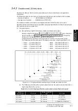
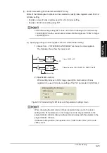
(1) Using bit devices
(a) By specifying a digit for bit devices, double word data can be used.
Specify a digit for bit data as '
'. (For a link direct
device, specify as 'J
\
'. To specify
X100 to X11F of Network No.2, specify as J2\K8X100.)
A digit cannot be specified in the range from K1 to K8 in unit of 4 points (4 bits).
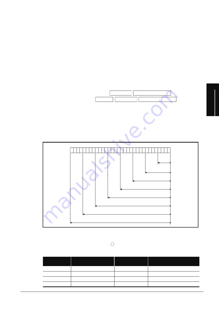
The followings are the examples of the target points when a digit is specified for X0.
Figure 3.4.3-1 Digit specification setting range of double word data (32 bits)
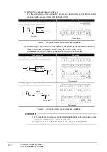
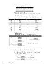
(b) The following table shows the numeric values that can be used as source data when a
digit is specified at the source .
Table 3.4.3-1 List of digit specification and numeric values that can be used
• K1X0 ...... 4 points of X0 to X3
• K5X0.......20 points of X0 to X13
• K2X0 ...... 8 points of X0 to X7
• K6X0.......24 points of X0 to X17
• K3X0 ...... 12 points of X0 to XB
• K7X0.......28 points of X0 to X1B
• K4X0 ...... 16 points of X0 to XF
• K8X0.......32 points of X0 to X1F
Number of
specified digits
Value range
Number of specified
digits
Value range
K1 (4 points)
0 to 15
K5 (20 points)
0 to 1048575
K2 (8 points)
0 to 255
K6 (24 points)
0 to 16777215
K3 (12 points)
0 to 4095
K7 (28 points)
0 to 268435455
K4 (16 points)
0 to 65535
K8 (32 points)
−
2147483648 to 2147483647
N
um
b
er
o
f
d
i
g
i
ts
Start
num
b
er
o
f bi
t
dev
i
ce
N
et
w
ork
N
o
.
N
um
b
er
o
f
d
i
g
i
ts
Start
num
b
er
o
f bi
t
dev
i
ce
X1F
X1
C
X1
B
X1
8
X1
7
X14 X1
3
X1
0
XF
X
C
X
B
X
8
X
7
X4 X
3
X
0
K1
s
p
ec
ifi
cat
i
on
range
(
4 p
o
i
nts)
K2
s
p
ec
ifi
cat
i
on
range
(8
p
o
i
nts)
K
3
s
p
ec
ifi
cat
i
on
range
(
12 p
o
i
nts)
K4
s
p
ec
ifi
cat
i
on
range
(
16 p
o
i
nts)
K5
s
p
ec
ifi
cat
i
on
range
(
2
0
p
o
i
nts)
K6
s
p
ec
ifi
cat
i
on
range
(
24 p
o
i
nts)
K
7
s
p
ec
ifi
cat
i
on
range
(
2
8
p
o
i
nts)
K
8
s
p
ec
ifi
cat
i
on
range
(3
2 p
o
i
nts)
s
Summary of Contents for MELSEC Q Series
Page 1: ...Structured Programming Manual Mitsubishi Programmable Controller QCPU Common Instructions ...
Page 2: ......
Page 14: ...A 12 MEMO ...
Page 340: ...6 178 MEMO MTR ...
Page 708: ...7 368 MEMO ...
Page 776: ...8 68 MEMO ...
Page 796: ...9 20 MEMO ...
Page 804: ...App 8 MEMO ...
Page 812: ...Index 8 MEMO ...
Page 815: ......


