3 - 5
3. SIGNALS AND WIRING
3.2 Signal terminal explanation
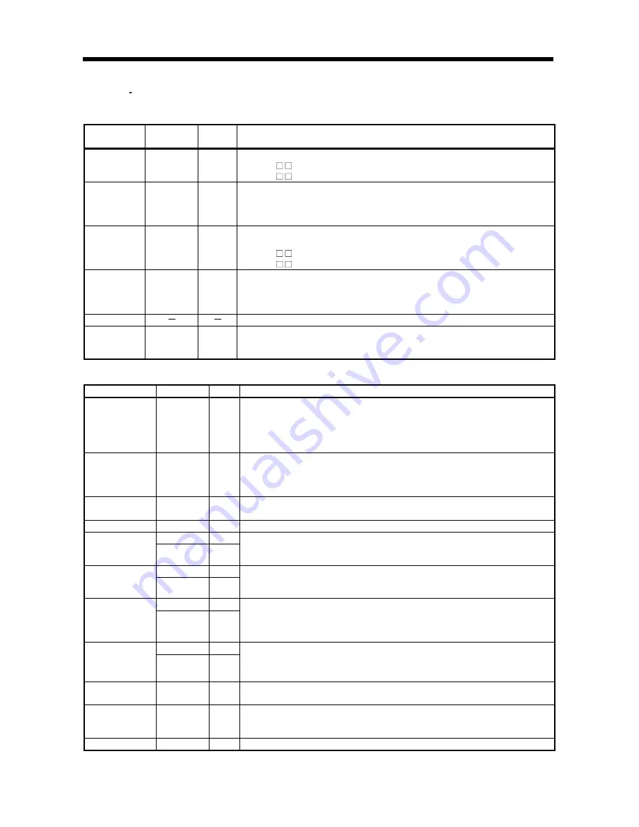
(1) Main circuit terminal block, control circuit terminal block
Signal Name Abbreviation
Termina
l Block
Description
Main circuit
power supply
L1, L2, L3
TE1
Main circuit power input terminals.
MR-J2S- B : Connect three-phase 200 to 230VAC/50, 60Hz.
MR-J2S- B1 : Connect single-phase 100 to 120VAC/50, 60Hz.
Servo motor
output
U, V, W
TE1
Servo motor power output terminals.
Connect to the servo motor power supply terminals (U, V, W).
During
power-on, do not open or close the motor power line. Otherwise, a
malfunction or faulty may occur.
Control
circuit power
supply
L11, L21
TE2
Control circuit power input terminals.
L11 should be in the same power supply phase with L1, and L21 with L2.
MR-J2S- B : Connect to single-phase 200 to 230VAC/50, 60Hz.
MR-J2S- B1 : Connect to single-phase 100 to 120VAC/50, 60Hz.
Regenerative
option
P, C, D
TE2
Regenerative option connection terminals.
Factory-wired across P-D.
When using the regenerative option, always remove the wire across P-D
and connect the regenerative option across P-C.
N
Keep open.
Protective
earth
PE
Chassis
Ground terminal.
Connect to the earth terminal of the servo motor and the protective earth of
the control box for grounding.
(2) CN3
Signal Name
Abbreviation Pin No.
Function/Application
Digital I/F power
supply input
COM
5
24VDC for input interface is input.
Digital interface driver power input terminal.
COM is all connected internally.
When using an external power supply, connect a power supply of 24VDC
and 200mA or more instead of VDD.
I/F internal
power supply
output
VDD
10
Digital interface driver power output terminal.
24VDC is output across VDD-SG. Connect with COM.
(Do not make connection when using an external power supply.)
The permissible current is 80mA.
Digital I/F
common
SG
3
24V common for VDD/COM and isolated from LG.
Control common
LG
1, 11
Control common used as a monitor common.
LA
6
Encoder
A-phase pulse
LAR
16
Encoder A-phase pulse output terminals.
The pulses set in parameter No. 38 (ENR) in the output type selected in
parameter No. 68 (FC2) are output in the differential line driver system.
LB
7
Encoder
B-phase pulse
LBR
17
Encoder B-phase pulse output terminals.
The pulses set in parameter No. 38 (ENR) in the output type selected in
parameter No. 68 (FC2) are output in the differential line driver system.
LZ
8
Encoder
Z-phase pulse
LZR
18
Encoder Z-phase pulse output terminals.
1 pulse is output per servo motor revolution.
By setting parameter No. 68 (FC2), the Z phase (reference mark) of the full
closed encoder can be output.
MO1
4
Monitor output
MO2
14
Monitor output signal output terminals.
The data set in parameter No. 22 (MOD) is output in analog form.
The multiplying factor can be set in parameter No. 22 (MOD).
Electromagnetic
brake interlock
MBR
13
MBR-SG are disconnected at servo-off or alarm. At alarm occurrence, they
are disconnected independently of the base circuit state.
Forced stop
EM1
20
When EM1-SG are opened, a forced stop state occurs, the servo switches
off, and the dynamic brake is operated to make a stop. The forced stop
signal can be made invalid using parameter No. 23.
Shield
SD
Plate Connect one end of the shield wire.
Summary of Contents for Melservo-J2-SUPER series
Page 19: ...1 6 1 FUNCTIONS AND CONFIGURATION MEMO...
Page 49: ...2 30 2 LINEAR SCALES MEMO...
Page 85: ...5 8 5 PARAMETERS MEMO...

