background image

CONTENTS

1. PRODUCT SPECIFICATIONS........................................................................................ 2
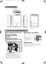
2. OUTER DIMENSIONS .................................................................................................... 3
3. EXTERNAL VIEW, PARTS AND DISPLAY SECTION................................................... 3
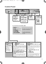
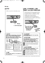
4. NAMES AND FUNCTIONS OF PARTS....................................................................... 4 ~ 8
5. TECHNICAL POINTS................................................................................................... 9 ~ 11
6. MAINTENANCE ......................................................................................................... 12 ~ 13
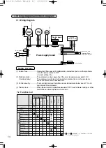
7. WIRING DIAGRAM AND BLOCK DIAGRAM

7.1 Wiring Diagram....................................................................................................... 14
7.2 Function List ....................................................................................................... 14 ~ 16
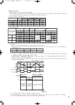
7.3 Timing Charts ..................................................................................................... 17 ~ 19
7.4 General Block Diagram ...................................................................................... 20 ~ 21

8. TROUBLESHOOTING PROCEDURE

8.1 Troubleshooting flowchart  ................................................................................. 22 ~ 23
8.2 Key Component Check Procedures ....................................................................... 24
8.3 Error Indications and Corrective Actions  ............................................................... 24
8.4 Self-Test Program and Execution Procedure  ........................................................ 25

9. DISASSEMBLY AND REASSEMBLY HINTS  .......................................................... 26 ~ 28

9.1 Disassembly Procedures ....................................................................................... 26

10. CONTINUOUS WATER DRAINAGE ............................................................................. 29
PARTS CATALOG  .......................................................................................................... 30 ~ 37
11. TROUBLESHOOTING ............................................................................................... 38 ~ 39
PRECAUTIONS ............................................................................................................... 40 ~ 42

ADVANCED AND EVER ADVANCING

MITSUBISHI ELECTRIC

DEHUMIDIFIER

2005

SERVICE MANUAL

MJ-E16V-S1

Model

Sold from 2005

No.MJW-0502A

Summary of Contents for MJ-E16V-S1

Page 1: ...Diagram 20 21 8 TROUBLESHOOTING PROCEDURE 8 1 Troubleshooting flowchart 22 23 8 2 Key Component Check Procedures 24 8 3 Error Indications and Corrective Actions 24 8 4 Self Test Program and Execution Procedure 25 9 DISASSEMBLY AND REASSEMBLY HINTS 26 28 9 1 Disassembly Procedures 26 10 CONTINUOUS WATER DRAINAGE 29 PARTS CATALOG 30 37 11 TROUBLESHOOTING 38 39 PRECAUTIONS 40 42 ADVANCED AND EVER ADV...

Page 2: ...s H W D mm Weight kg Coolant quantity g Evaporator Condenser Model 30 C room temperature 80 relative humidity liters day Laundry Low Performance Product performance Compressor Blower Electrical characteristics Operating noise levels dB Compressor protection Model Output W Winding resistance Ω 20 C Blower protection Type Output W Flow rate selection Speed rpm Flow rate m3 min Operating room tempera...

Page 3: ... vertical position Blowing air at the wall may cause staining Operating noise Place the unit on top of a mat This reduces vibration and noise It also prevents leaving depressions on carpets At least 50 cm At least 2 cm At least 20 cm At least 20 cm At least 20 cm Direct the louvres at the laundry Space laundry to improve airflow Drying times will vary depending on the nature of the laundry and the...

Page 4: ...nsport Pre filter Water tank Front panel Louvre Continuous drainage outlet Tank lid Floating element Front door The water tank may contain water residue at time of purchase This is from final product testing at the factory and is not due to a defect It is impossible to remove the back panel because the two spots shown are fastened with two special screws If the unit malfunctions contact your Mitsu...

Page 5: ... DEFROST will start automatically when room temperature drops below 15 C This may be as often as once every 40 minutes The unit automatically shuts down and indicates with the lamp and sound that the water tank is full Empty the water tank Tank full lamp lights The unit beeps Airflow stops Lamp turns off After removing the water and replacing the tank the Tank full lamp will go off and then the un...

Page 6: ...tte smoke and toxins found in smoke such as carbon monoxide cannot be removed with these filters Humidity level Room temperature C 50 20 30 27 60 Room temperature is below 27 C the unit automatically sets the humidity level according to the temperature Room temperature is above 27 C the unit lowers the humidity level to 50 then activates the blower The dehumidifier is reactivated when humidity ris...

Page 7: ...oom The moisture expelled from inside the unit may smell due to odorants that were not caught by the filter dissolving in the water The OFF timer cannot be set during drying inside Information OFF Regular Regular operation operation Dehumidifier Air purifier Drying inside operation approx one hour Airflow Approx 30min Airflow stops compressor activates operating sound Compressor operates according...

Page 8: ...ontinue operation Hold down the button until the OFF Timer lamp goes out The unit returns to Low mode Press Empty the water tank before operating The unit stops and the Tank full lamp lights if the tank becomes full during operation The OFF timer cannot be set while drying inside is operating Information If the lid is not properly closed you may have problems removing the tank If the tank is not i...

Page 9: ... damage the home or clothing when closets dressing rooms shoe cabinets and other spaces where humidity is prone to collect are not dehumidified A single high capacity unit is effective in dehumidifying and drying various locations throughout the home quickly moving from one point to the next 3 Room humidity and sensible temperature comfortably controlled The EASY DEHUMIDIFYING mode controls humidi...

Page 10: ...ing internal frost into the water tank The unit will resume automatically when the defrost operation completes This operation will be performed automatically when the room temperature is approximately 15 C or lower When humidity is high this will occur approximately once every 40 minutes for 5 10 minutes How does the dehumidifier work If you pour cold water into a cup the air around it becomes col...

Page 11: ...ected is decreased In winter because the temperature is lower than in summer the effects of the dehumidifier decrease dramatically as shown in the graph below Although less water collects in the tank this is not a malfunction Summer humidity Winter dampness If the temperature is low but the humidity is high due to snow or rain operating the unit in LOW TEMP mode will yield better results than in L...

Page 12: ...bs of the pre filter Front panel Pre filter Honeycomb side Tabs 6 Air purifying filter Pre filter Water tank Main unit Wipe with a soft cloth Floating element Do not remove or dismantle Do not remove the louvre front door Pre filter 1 Remove the front panel and pre filter 2 Remove the air purifying filter 5 Attach the pre filter and front panel 4 Fit the air purifying filter 3 Clean the pre filter...

Page 13: ...urifying filter 3 Attach air filter and front panel After switching the unit off leave for one day until any water inside has had time to run off then carry out the following steps 1 Perform drying inside Performing drying inside to prevent mildew growth is recommended 2 Bundle power cord 3 Remove the drainage water Empty the water tank and wipe away any remaining drops of water 4 Clean the pre fi...

Page 14: ...rrent setting 2A 2 Motor protector The compressor stops operating if the room temperature exceeds 35 C Overload relay The compressor will also shut down when malfunctions or other problems cause the current flow to exceed 5 3A 3 Control circuitry The room temperature thermister senses temperature below about 0 C and shuts down the compressor 4 Thermal fuse When blower motor temperature exceeds 133...

Page 15: ...ty rises above 60 and returns to CIRCULATE mode when the humidity drops below 50 0 60 ON ON OFF OFF OFF OFF ON ON 60 60 50 50 50 1 2 3 Current humidity Set humidity 20 C 27 C 34 C 3 1 5 1 Temperature Temperature table Set humidity Dehumidification Fan rank Compressor Fan rank Compressor Fan rank Compressor 22 C 29 C 36 C Rank 1 Rank 1 ON ON Rank 1 Rank 1 Rank 2 Rank 2 ON ON Circulate To Dehumidifi...

Page 16: ...he temperature rises too high Step 5 Internal humidity is discharged in Step 4 c Step 3 does not perform the tube temperature or room temperature check that accompanies a microprocessor reset and jumps directly to Step 5 d Mechanisms operated in the above steps are deemed E2 PROM data 4 Conditions for drying inside operation to end a Upon completion of step 5 above b The following buttons terminat...

Page 17: ...OFF Compressor ON OFF Float switch Lo Blower fan Tank full Drain Power OFF Humidify Easy dehumidifying Mode max 3 min 3 sec Mi for 2 sec at start up min 7 min Lo ON OFF Tank full light Lo 50 Low temp Room temperature Low temp Decrease in room temperature Increase in room temperature 3 sec 14 16 When room temperature is between 20 and 27 7 3 Timing Charts ...

Page 18: ...Compressor ON OFF Solenoid valve Tube temperature Defrost ON OFF Blower fan 40 min ON OFF Operation switch After 4 hr Defrost start Defrost finish ON OFF Timer lamp ON OFF Mode lamp After 1 hr After 2 hr Off timer ON Off timer ON Off timer ON 4 hr 2 hr 2 hr 12 0 ...

Page 19: ...FF Blower fan ON OFF Operation switch Cleaning inside complete Cleaning inside complete ON OFF Cleaning inside switch ON OFF Operation mode lamp max 20 min 30 min 60 min 10 min Operation OFF Start Cleaning inside Cleaning inside automatic max 20 min Cleaning inside switch ON 30 min 10 min 60 min Tube temperature 45 Tube temperature 45 45 45 ...

Page 20: ...20 7 4 General Block Diagram ...

Page 21: ...21 ...

Page 22: ...g removed from the receptacle remove and insert each connector two to three times to improve its contact Then insert the power plug into the receptacle to make an operation check Make sure that the flat cable and the connectors are inserted straight Check operation Step 1 Step 2 Dehumidifier doesn t operate at all A Does the fan operate Set mode to LOW Check connectors NO NO NO YES Are the resisto...

Page 23: ...tube temperature sensor should be at least 10 C lower than room temperature when normal Are the power consumption and current normal Is the filter blocked Is the operating environment low humidity or low temperature Clean filter Dehumidification may not be possible in low humidity and low temperature environments See page 10 Is dehumidification taking place Water drops are being collected Recheck ...

Page 24: ...inals using a multimeter winding temperature 10 C to 30 C 2 6kΩ 2 9kΩ Open or shorted Normal Abnormal 25 0Ω 27 1Ω 67 9Ω 73 5Ω C R side C S side Open or shorted Normal Abnormal 258Ω 280Ω 379Ω 411Ω Yellow Blue Black Blue Stepping motor Measure the resistance across terminals with a multimeter Part temperature approx 25 C Open or shorted Normal Abnormal 342Ω 418Ω Terminals 1 2 Terminals 1 3 Terminals...

Page 25: ...and AUTO buttons together 4 times when the power is off Press the POWER button within 2 seconds Mode selection Use the AUTO button to change through the self test modes Sensor disconnection short circuit check Lights all LEDs Indicates Board type switch data and or Micropr ocessor version Indicates EPROM2 data version Humidity detected by humidity monitor Indicates error history error count Tube t...

Page 26: ...crew two 4x14 P100 Catch Water tank 3 Removing the front casing assembly Step 1 Remove the water tank and front panel following the steps for sections 1 and 2 above Step 2 Remove front casing set screws two 4x14 four 4x12 Pic 2 Step 3 Pull the front casing assembly toward you so that it is away from the main unit Pic 3 Step 4 Pull the power board box toward you detach the catches on the box lid on...

Page 27: ...l and front casing assembly following the steps for sections 1 to 3 above Step 2 Remove the rear casing setscrews 6 Pic 9 Step 3 Push the rear casing downward and pull outward to detach the catches on the bottom Lift the rear casing and raise the handle Detach the catches that prevent the handle from coming loose and remove the handle Pic 10 Step 4 Pull the top part of the rear casing outward and ...

Page 28: ...sing Step 4 Remove the power board box assembly Pic 13 Step 5 Detach the catches one on each side that interlock the fan assembly and the drain pan by leaning the top of the fan assembly toward the heat exchanger and pulling upward Remove the fan assembly Pics 14 15 Repairable parts Fan Fan motor Float switch Heat exchanger radiator refrigerator Picture 13 Picture 14 Picture 15 Picture 16 Valve Bo...

Page 29: ...The water will not drain Note Leave a minimum space of 20 cm behind the unit for attaching the hose Confirm that the hose does not show signs of deterioration such as cracks and clogging Inspect the hose every 2 weeks Insects or dirt blocking the hose may cause leakage resulting in malfunctions How to set up the drainage hose Correctly installed Incorrectly installed Necessary items Commercially a...

Page 30: ...30 Model MJ E16V S1 Exploded View Casing and Structure 5 1 A C B 15 4 13 16 17 18 14 2 3 6 10 11 12 9 8 7 20 19 21 magnifing picture 22 Parts Catalog ...

Page 31: ...eous Pc 1 unit Safety Part M22 B15 738 M22 B19 741 M22 B15 697 M22 B25 379 M22 B25 233H M22 C45 440 M22 C45 450M M22 B16 978 M22 B19 781 M22 B24 001 M22 B30 100 M48 5C5 813 M22 B25 232 M22 B25 063 M22 B15 290 M22 C44 700 M22 C44 501 M22 B15 218 M22 B15 222 M22 B15 223 M22 B25 224 M22 B15 128 1 1 1 1 1 1 1 1 1 1 1 1 1 1 1 1 1 2 1 1 1 1 4 2 7 TANK S X COVER TANK 100T LID TANK S X FLOAT ASSY 100S X C...

Page 32: ...32 Model MJ E16V S1 Exploded View Casing and Structure 34 25 26 28 30 31 33 32 27 29 35 36 37 Parts Catalog ...

Page 33: ...thout part numbers use the design number The order may take a while to process Part No Exploded View Matching No Part Name Compatibility Miscellaneous Pc 1 unit Safety Part M22 B15 788 M22 J67 923 M22 B15 219 M22 B25 113 M22 J67 034 M22 C01 353 M22 B19 130 M22 B25 081 M22 B25 114 M22 C22 512 M22 B25 045 M22 B15 036 M22 B24 994 M22 C45 450 M22 C45 791 1 1 2 1 1 1 1 1 1 1 1 1 1 1 1 1 STOPPER PLATE 1...

Page 34: ...34 Model MJ E16V S1 Exploded View Electrical Parts 3 B C 5 4 2 1 6 D 9 8 7 A E Parts Catalog ...

Page 35: ...mmon part 2 Parts found installed in products may have a different part number from service parts However there should be no difference inperformance and can be installed Notes 1 Circled reference numbers indicate performance parts 2 New parts and the parts that are used only with these models lack compatibility 3 Those parts that are marked by and are of critical importance for sustaining safety ...

Page 36: ...36 Model MJ E16V S1 Exploded View Compressor Parts 10 7 22 20 8 9 6 5 4 12 18 19 1 2 3 A 11 13 14 15 17 16 21 back Parts Catalog ...

Page 37: ...t No Exploded View Matching No Part Name Compatibility Miscellaneous Pc 1 unit Safety Part M22 C44 629 M22 C50 629 M22 C44 555 M22 B19 630 M22 B31 620 M22 B15 018 M22 J16 923 M22 C13 820 M22 B15 653 M22 C29 645 M22 B15 221 M22 B15 650 E16SX A1 1 1 1 1 1 1 1 1 1 1 1 1 1 1 1 1 1 1 1 1 1 1 1 S COIL TAPE ASSY EVX SOLENOIDO VALVE R TAPE THERMISTOR EVA W X COOLER 100T X CONDENSER 100W X CLIP TERMINALCOV...

Page 38: ...g the air intake or outlet Remove the obstruction Check to see if the pre filter is clogged Clean according to the maintenance procedures Check to see if the unit is in AUTO The unit is automatically controlling the dehumidifier fan and standby times Check to see if the water tank is full Empty the water tank and return it to its original position Check to see if the water tank is inserted properl...

Page 39: ...e the compressor operates intermittently causing the sound to be heard occasionally The compressor does not activate after turning the unit off or for 3 minutes after plugging the unit into a power socket This is to protect the compressor from damage The heat converter heats rapidly causing a brief odour This is not a malfunction The moisture expelled from inside the unit may smell due to odorants...

Page 40: ...ff the power plug and insert the plug firmly If the plug is not fully inserted into the socket dust may gather on the connectors which may cause fire and or electric shock Use 220 240V AC power sockets Connecting to power sockets other than 220 240V AC may result in fire and or electric shock Remove water that has collected in the tank Accidentally drinking the water or using it for other purposes...

Page 41: ...body for long periods it may harm one s physical condition and lead to dehydration Install the unit in a location where the floor is flat and stable If the unit falls over the water collected in the water tank may leak damaging surrounding objects and in turn result in fire or electric shock caused by an electrical leak Grasp the plug and remove from the power socket When removing the plug from th...

Page 42: ... the floor When using the continuous drainage outlet make sure to position the hose so that the water drains without obstruction The water in the tank may leak and damage surrounding objects When draining water continuously or left unattended for long periods inspect the unit every two weeks Do not allow debris to clog the filter hose as this may cause over heating leakage Use the unit with cautio...

Page 43: ...43 Packaging diagram ...

Page 44: ...Issued in 2005 07 Printed in Japan ...

Reviews: