3. SIGNALS AND WIRING
3 - 39
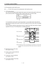
(2) INP (In-position)
INP turns on when the number of droop pulses in the deviation counter falls within the preset in-position
range ([Pr. PA10]). INP may turn on continuously during a low-speed operation with a large value set as
the in-position range.
In-position range
INP (In-position)
ON
OFF
ON
OFF
Alarm
No alarm
SON (Servo-on)
Alarm
Droop pulses
(3) RD (Ready)
RD (Ready)
ON
OFF
ON
OFF
Alarm
No alarm
SON (Servo-on)
Alarm
100 ms
or shorter
10 ms or shorter
10 ms or shorter
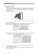
(4) Electronic gear switching
The combination of CM1 and CM2 enables you to select four different electronic gear numerators set in
the parameters.
As soon as CM1/CM2 is turned on or off, the numerator of the electronic gear changes. Therefore, if a
shock occurs at switching, use the position smoothing ([Pr. PB03]) to relieve the shock.
(Note) Input device
CM2 CM1
Electronic gear numerator
0 0
Pr.
PA06
0 1
Pr.
PC32
1 0
Pr.
PC33
1 1
Pr.
PC34
Note. 0: Off
1: On
Summary of Contents for MR-J4-100A
Page 9: ...A 8 MEMO ...
Page 61: ...1 FUNCTIONS AND CONFIGURATION 1 44 MEMO ...
Page 67: ...2 INSTALLATION 2 6 MEMO ...
Page 137: ...3 SIGNALS AND WIRING 3 70 MEMO ...
Page 261: ...6 NORMAL GAIN ADJUSTMENT 6 24 MEMO ...
Page 291: ...7 SPECIAL ADJUSTMENT FUNCTIONS 7 30 MEMO ...
Page 299: ...8 TROUBLESHOOTING 8 8 MEMO ...
Page 319: ...9 OUTLINE DRAWINGS 9 20 MEMO ...
Page 461: ...12 ABSOLUTE POSITION DETECTION SYSTEM 12 36 MEMO ...
Page 511: ...14 COMMUNICATION FUNCTION 14 38 MEMO ...
Page 559: ...16 USING A DIRECT DRIVE MOTOR 16 20 MEMO ...
Page 583: ...17 FULLY CLOSED LOOP SYSTEM 17 24 MEMO ...
Page 621: ...APPENDIX App 38 ...
Page 639: ......


