3. SIGNALS AND WIRING
3 - 53
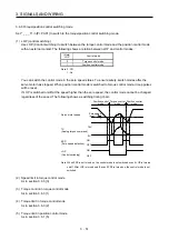
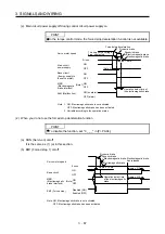
(2) Timing chart
POINT
When LSP/LSN is turned on during a forced stop deceleration, the motor will
stop depending on the setting of [Pr. PD30] as follows.
[Pr. PD30]
Stop system
_ _ _ 0
Switching to sudden stop
_ _ _ 1
Continuing forced stop deceleration
When EM2 (Forced stop 2) turns off, the motor will decelerate according to [Pr. PC51 Forced stop
deceleration time constant]. Once the motor speed is below [Pr. PC17 Zero speed] after completion of
the deceleration command, base power is cut and the dynamic brake activates.
Base circuit
(Energy supply to
the servo motor)
0 r/min
Servo motor speed
MBR
(Electromagnetic
brake interlock)
ON
OFF (Enabled)
ON
OFF
Deceleration time
Command
Rated speed
Ordinary
operation
Forced stop
deceleration
Dynamic brake
+
Electromagnetic brake
ON
OFF (Enabled)
EM2 (Forced stop 2)
Zero speed
([Pr. PC17])
[Pr. PC51]
Summary of Contents for MR-J4-100A
Page 9: ...A 8 MEMO ...
Page 61: ...1 FUNCTIONS AND CONFIGURATION 1 44 MEMO ...
Page 67: ...2 INSTALLATION 2 6 MEMO ...
Page 137: ...3 SIGNALS AND WIRING 3 70 MEMO ...
Page 261: ...6 NORMAL GAIN ADJUSTMENT 6 24 MEMO ...
Page 291: ...7 SPECIAL ADJUSTMENT FUNCTIONS 7 30 MEMO ...
Page 299: ...8 TROUBLESHOOTING 8 8 MEMO ...
Page 319: ...9 OUTLINE DRAWINGS 9 20 MEMO ...
Page 461: ...12 ABSOLUTE POSITION DETECTION SYSTEM 12 36 MEMO ...
Page 511: ...14 COMMUNICATION FUNCTION 14 38 MEMO ...
Page 559: ...16 USING A DIRECT DRIVE MOTOR 16 20 MEMO ...
Page 583: ...17 FULLY CLOSED LOOP SYSTEM 17 24 MEMO ...
Page 621: ...APPENDIX App 38 ...
Page 639: ......


